Currently, the widely used bending force calculation formulas have been adopted from foreign sources without any information about their origin or scope of application.
This article presents a systematic analysis of the process of deriving the bending force calculation formula, as well as the required parameters.
Furthermore, a new approach to calculate bending force is introduced to expand its scope of application.
V and U shaped bending strength calculator
Sheet Metal Bending Strength Formula
In recent years, the bending machine has gained widespread use in various industries and expanded its processing capabilities.
Despite its popularity, there has been a lack of systematic discussion about calculating bending strength.
Currently, there are approximately two types of bending force calculation formulas recommended by the product manuals of different press brake manufacturers.
In the formula:
- P- bending force, kN;
- S- sheet thickness, mm;
- l –fold length of the sheet, m;
- V- width of the lower opening of the matrix, mm;
- σ b – tensile strength of the material, MPa.
The manufacturer's recommended formula for calculating bending force is based on a previously mentioned formula.
Both formulas have been taken from various product brochures, however, there is no proof of their accuracy.
Related Calculator: Press Brake Tonnage Calculator
The process of obtaining the bending force calculation formula, as well as its applicable scope.
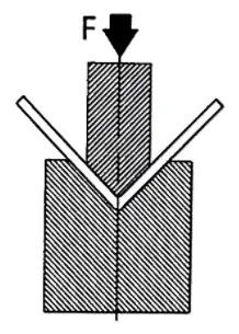
Figure 1 is a schematic representation of the sheet metal bending process.
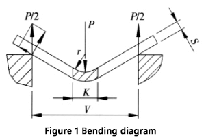
- Q: Bending strength
- S: Sheet thickness
- V: Width of the lower opening of the matrix
- r: Internal radius during the bending process
- K: Width of the horizontal projection of the deformation zone during bending.
The calculation of the bending force and its parameters are explained below:
The recommended width of the lower die opening (V) for free bending is 8 to 10 times the sheet thickness (S), with a width/thickness ratio of V/S = 9.
Press brake manufacturers provide values for the die width (V) and inner radius (r) of the bent part in their bending force parameter table. The radius-to-width relationship is generally r = (0.16 to 0.17) V and in this case the value of 0.16 is used.
During the bending process, the material in the deformation zone undergoes significant plastic deformation, causing it to bend around the center line.
In some cases, small cracks may appear on the outer surface of the curved area.
The stress in the deformation zone, except near the central layer, is close to the tensile strength of the material, with the upper part of the neutral layer being compressed and the lower part under tension.
Figure 2 illustrates the cross section and the corresponding stress diagram in the deformation zone.
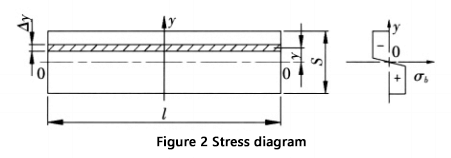
- Sheet thickness S
- l- sheet bend length
The bending moment in the deformation zone section is:
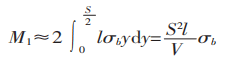
The bending moment produced by the bending force in the deformation zone is shown in Figure 1.
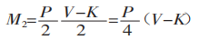
From 1 =M 2 We have:
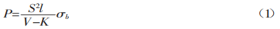
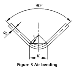
When bending a sheet with a universal die on a press brake, as shown in Figure 3, most sheets are bent at 90°. In this case, K is:
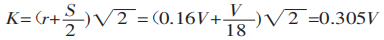
Substituting K into equation (1), we obtain:
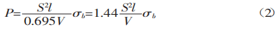
The tensile strength of common materials, σb, is 450 N/mm². This value can be used in formula (2) to calculate the result.
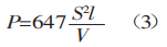
The bending force calculation formula obtained here is in accordance with the information provided in foreign brochures.
The variables in the formula are:
- S: Sheet thickness
- r: Internal radius when the sheet is bent
- K: Width of the horizontal projection of the flexural deformation zone.
As can be seen from the derivation process, when using formulas (2) or (3) to calculate the bending force, it is important to ensure that two additional conditions are met: the width to thickness ratio (V/S) must be equal to 9, and the ratio between radius and width must be equal to 0.16.
If these conditions are not met, significant errors may occur.
New Methods and Steps for Calculating Bending Forces
Bending force calculation can be complicated when it is not possible to meet the two additional requirements (width/thickness ratio V/S = 9 and radius/width ratio = 0.16) due to design or process limitations.
In these situations, it is advisable to follow these steps:
- Calculate the width-to-thickness ratio and radius-to-width ratio based on the plate thickness (S), radius of curvature (r), and die bottom opening (V).
- Determine the projection width of the deformation zone considering the deformation of the sheet.
- Use formula (1) to calculate the bending force, taking into account any differences in the radius of curvature and the corresponding deformation zone.
These steps will provide a more accurate and reliable result compared to using the commonly used formula. An example to illustrate this process is shown in Figure 4.
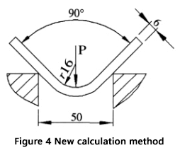
Data: Sheet thickness (S) = 6mm, Sheet length (l) = 4m, Curvature radius (r) = 16mm, Bottom width of the die opening (V) = 50mm and Tensile strength of the material (σb) = 450N/mm².
Question: How can we calculate the bending force required for air bending?
Here are the steps:
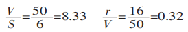
First, calculate the width-to-thickness ratio and the radius-to-width ratio:
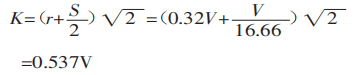
Then calculate the projected width of the deformation area:
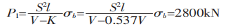
Finally, use formula (1) to calculate the bending force:
If the normally recommended formula is used to calculate bending force:
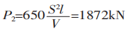
It can be inferred from P1/P2 = 1.5 that the difference between P1 and P2 is 1.5 times.
The reason for this discrepancy is because in this example the radius of curvature is relatively large, which results in an increase in the deformed area and therefore requires a greater bending force.
The ratio of radius to width in this example is 0.32, which exceeds the previously mentioned criteria.
Using the standard formula to calculate bending force is not suitable for this scenario. The advantages of using the new calculation method can be seen in this example.
Additionally, there is an online calculator available to calculate bending force using the new method.
Tensile Strength Table
| Material | Tensile strength | ||
|---|---|---|---|
| American | European | China | N/mm² |
| 6061 Aluminum | Alu50 | LD30 | 290 |
| 5052 Aluminum | Alu35 | LF2 | 303 |
| 1010 mild steel | DC01 | 10/10F | 366 |
| A 536 -80 G 60-40-18 | GGG-40 | QT400-18 | 400 |
| A 351 G CF 8 | GX 6CrNi 18 9 | Q235 | 450 |
| A 572 G50 | S 355MC | Q345 | 550 |
| 304 Stainless | Stainless V2A | 0Cr18Ni9 | 586 |
| 316 Stainless | Stainless steel V4A | 0Cr17Ni12Mo2 | 600 |
| 4140 Low alloy | 42CrMo4 | 42CrMo | 1000 |
Bending force calculation formulas for coining
The formulas for calculating coining parameters are different from the air bending formulas.
1. V-die width:
V = sheet metal thickness × 5
2. The internal radius is determined by the punch tip, which must be chosen according to the following formula:
Radius = sheet metal thickness × 0.43.
3. Force required for coining:
F( kn/m) = Thickness 2 ×1.65×Tensile strength (N/mm 2 )×4.5/Vee width of the matrix
4. The minimum internal edge calculation formula remains the same:
Minimum inner edge = Die vee × 0.67
Bending force calculation formulas for Z bending
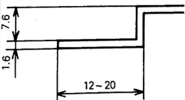
Some tools require a specific force to yield the sheet metal and manage the springback to obtain the required profile.
As an example we will consider joggle tools, which make two bends at the same time with a short distance between the bend and the counter bend.
Since these tools make two bends at the same time, the springback must be completely canceled by coining.
The equation to calculate the required force is:
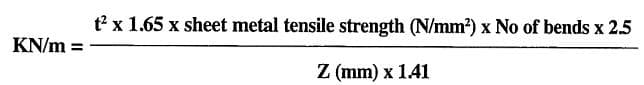
- KN/m = force required per meter
- Z = oscillation in mm
- Number of curves = for a Z, assume 2
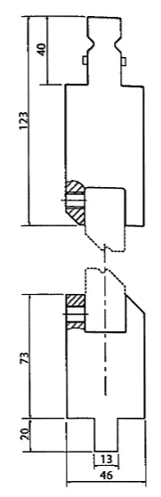
Joggle tools usually consist of an insertion bracket into which Joggle tools chosen according to the joggle and required angle are fixed with grub screws.
It is important to consult the manufacturer before purchasing, as these systems can only bend thin sheets, maximum 2mm, but the maximum thickness will depend on the type of insert and may be less than 2mm.
Conclusion
The formulas and steps provided for calculating bending force are suitable not only for angular bending of a sheet metal, but also for arc-shaped bending (which technically should be called angular bending with a large radius of curvature).
It's crucial to keep in mind that forming an arch shape requires a unique mold design.
When designing the deformation area, the calculation must be based on the process parameters established during the process, which cannot be determined through a single formula.
In a specific iron tower factory, we successfully bent a cylinder with a wall thickness of 12 mm, a diameter of 800 mm and a length of 16 m using a 28,000 kN press brake and a circular mold.
The method described in this article was used to determine the bending force and produced satisfactory results when designing an arc-shaped mold.
Further reading:
- Overhead push-up strength chart: Amada's most reliable data