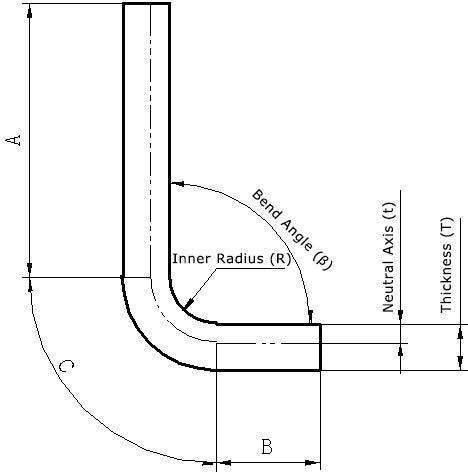
What is the K factor?
K-factor is a fundamental concept in SolidWorks sheet metal design and is crucial to mastering sheet metal fabrication.
You must first understand the K factor.
It is the ratio of the distance between the neutral layer and the inner surface of the bend and the thickness of the metal sheet.
As shown in the diagram below, K =t/T . From the definition of the K factor, it is clear that it is a constant greater than 0 and less than 1.

Since the K factor is related to the position of the neutral layer, what is the neutral layer?
In the flexural deformation zone, material near the inner surface is compressed, and the compression is more severe the closer it is to the inner surface.
Likewise, material close to the outer surface is stretched, and the stretching is more severe the closer it is to the outer surface.
The transition from compression to stretching, going from the inner surface to the outer surface, assuming the material is stacked in thin layers (most metallic materials are layered), there should be a layer in the middle of the material that is neither compressed nor stretched . We call this layer the neutral layer.
In general, the neutral layer cannot be seen or touched because it is inside the metal. Its position is related to the inherent properties of the material, which means that the K factor is related to the material. According to the definition of the neutral layer, the unfolded size of the sheet is equal to the width of the neutral layer, as shown in the figure above.
The unfolded size of the sheet = straight line A + straight line B + arc C (length of the neutral layer in the deformation zone).
The K factor is also known as the neutral layer position factor. For most materials, the K factor is a number less than or equal to 0.5 in sheet metal design and processing.
How to calculate the K factor?
The k factor is an independent value that describes how sheet metal bending occurs in a wide range of geometric parameter situations and how it unfolds. It is also an independent value used to calculate bend tolerance (BA) in various situations, such as material thickness, bend radius/angle.
The figures below can help us better understand the detailed definition of the k-factor.

In the thickness of sheet metal parts, there is a neutral layer or axis. The sheet metal material in the neutral layer of the bending area does not stretch or compress, which is the only place in the bending area where it remains undeformed. It is represented as the intersection of the pink and blue areas in the diagram.
During the bending process, the pink area is compressed, while the blue area is stretched. If the neutral layer of the sheet metal remains undeformed, then the arc length of the neutral layer in the bending area is the same in its bent and flattened states.
Therefore, the bending tolerance (BA) must be equal to the arc length of the neutral layer in the bending area of the sheet metal part. This arc is represented in green in the Figure.
The position of the neutral layer in the sheet metal depends on the specific properties of the material, such as ductility.
Assuming that the distance between the neutral layer of the sheet metal and the surface is “t”, that is, the depth from the surface of the sheet metal part to the sheet metal material in the thickness direction is t.
Therefore, the arc radius of the neutral sheet metal layer can be expressed as (R+t).
Using this expression and the bending angle, the arc length of the neutral layer (BA) can be expressed as:
To simplify the definition of the neutral layer in sheet metal and considering the applicability to all material thicknesses, the concept of k factor is introduced. Specifically, the k factor is the ratio between the thickness of the neutral layer position and the total thickness of the sheet metal part, that is:
Therefore, the value of K is always between 0 and 1. If a factor k is 0.25, it means that the neutral layer is located at 25% of the thickness of the sheet metal material, and if it is 0.5, it means that the a neutral layer is located in half of the entire thickness and so on.
Combining the two equations above, we can obtain the following equation:
Where some values such as A, R and T are determined by the real geometric shape.
K Factor Calculator
We provide two different calculators to calculate the k-factor value. The final results may have slight differences, but they will definitely meet your needs.
Calculator #1
If the bend tolerance and inner bend radius are known, you can use the following calculator to calculate the k-factor as well as the distance from the inner surface to the neutral axis.


