Calculating brake tonnage
You can use the following way to calculate press brake tonnage to determine the bending force required for sheet metal bending. The calculator provides metric and imperial units. I personally recommend using the press brake tonnage calculator below as it is probably the best and most convenient method for calculating the required bending force.
The recommended V-opening width for the bottom die
| s | 0.5-3mm | 3-8mm | 9-10mm | >12mm |
| V | 6*S | 8*S | 10*S | 12*S |
For example, if the sheet to be bent is mild steel, with a thickness of 4 mm and a bending length of 3.2 m, the theoretical width of the bottom opening of the die should be 8 times the thickness, which is 32 mm. Insert these numbers into the calculator above (remember that the units are in mm) and we will obtain a value of 106.12 Ton.
This means you will need a minimum bending force of 106 tons to meet your bending needs. Of course, we usually multiply the final result by a safety factor of 1.1, and the resulting value is the tonnage of the press brake you can choose.
New tonnage calculation method
If the width/thickness (V/S) ratio is not equal to 9 and the radius/width ratio is not equal to 0.16, the above calculator will not be valid.
Review the updated method for calculating bending force on a bending machine.
Use the following bending strength calculator.
Calculating Bending Force in V and U Shape
The magnitude of the bending force is influenced by factors such as the size of the part, the mechanical properties of the material, the distance between the die fulcrums, the relative radius of curvature, the clearance between the dies, the coefficient of friction between the material and the matrix, the minimum bending angle and the bending method.
Consequently, it is difficult to calculate the bending force accurately in theory.
In practice, empirical formulas or simplified theoretical formulas are commonly used for calculation.
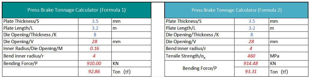
Pressure brake tonnage calculation formula
Currently, there are two main formulas for calculating press brake tonnage that are popular.
The first formula is commonly used in China and the second in other countries.
However, regardless of the formula used, the calculated required pressure of the press brake is basically the same. Let me present these two formulas separately below.
Bending Tonnage Calculation Formula #1
Where,
- P – Bending pressure, kN
- S – Thickness of the metal sheet, mm
- L – Length of metal sheet, mm
- V – Width of the lower opening of the matrix, mm
For example:
Plate thickness S=4mm, width L=3m, σb=450N/mm²
Generally slot width V=S*8
Therefore P=650* 4² *3/4*8=975 (KN) = 99.5 (ton)
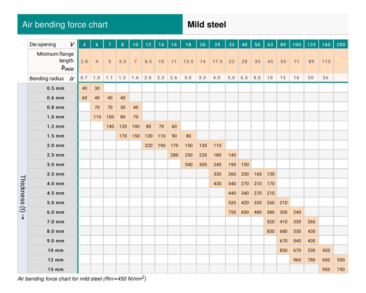
The result obtained using the bending force formula is very similar to the data in the bending force graph.
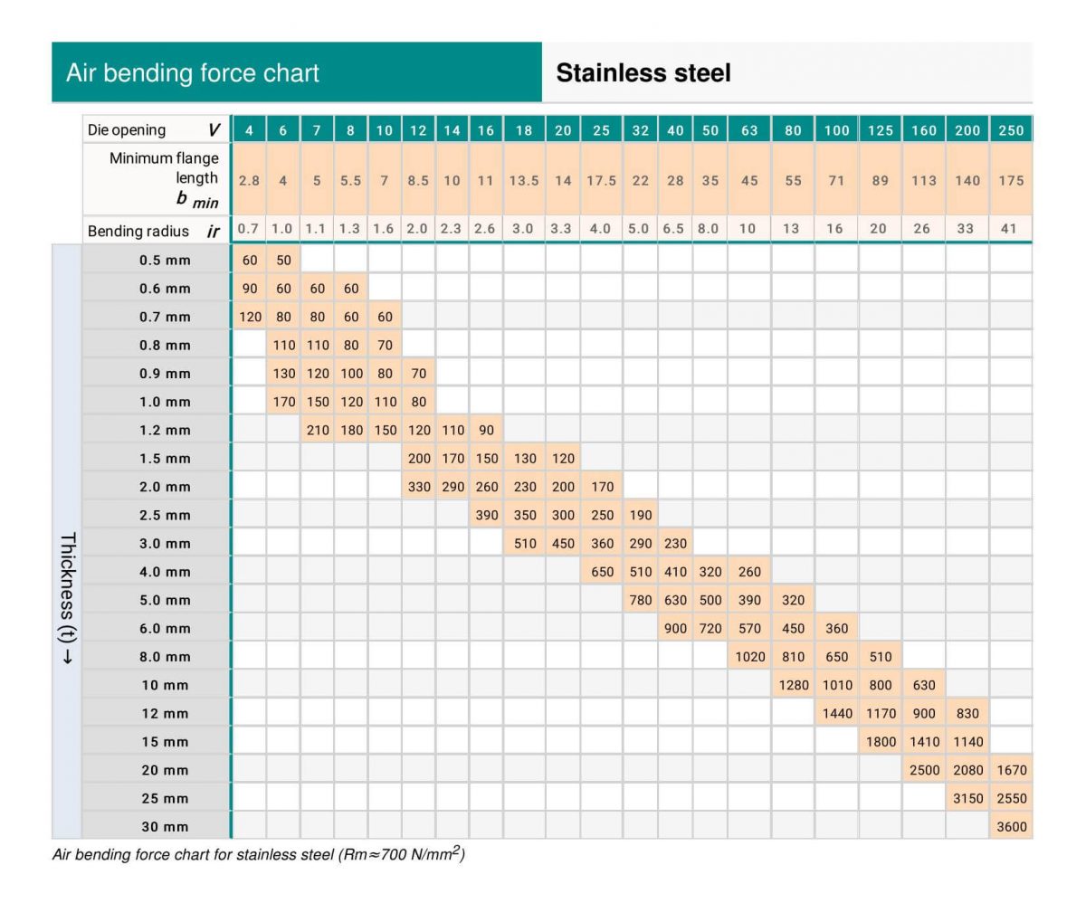
Please note that the #1 method for calculating press brake tonnage is based on carbon steel material.
If the material is stainless steel, aluminum, or brass, you can easily adjust the calculation results by multiplying them by the coefficients listed in the following table.
| Material | Coefficients |
| mild steel | 1 |
| Stainless steel | 1.6 |
| Aluminum | 0.65 |
| Brass | 0.5 |
#2 Bending tonnage calculation formula
- P – Bending force (KN)
- S – Plate thickness (mm)
- L – Board width (m)
- V – Width of the lower die slot (mm)
- σ b – Tensile strength (Mpa)
For example:
Plate thickness S=4mm, width L=3m, σb=450N/mm²
Generally slot width V=S*8
Therefore P=1.42* 450 *4²* 3/4 8 = 958.5 (KN) = 96 (ton)
The key to bending sheet metal with different materials is to determine the tensile strength of that specific material and then calculate the required bending force using the formula above.
The tensile strength table below can be the reference:
| Material | Soft (N/mm²) | Hard (N/mm²) |
|---|---|---|
| Lead | 25 – 40 | – |
| Tin | 40 – 50 | – |
| Aluminum | 93 | 1710 |
| Type 4 Aluminum Alloy | 230 | 480 |
| Duralumin | 260 | 480 |
| Zinc | 150 | 250 |
| Copper | 220 – 280 | 300 – 400 |
| Brass (70:30) | 330 | 530 |
| Brass (60:40) | 380 | 490 |
| Phosphor Bronze / Bronze | 400 – 500 | 500 – 750 |
| Nickel silver | 350 – 450 | 550 – 700 |
| Cold rolled iron | 320 – 380 | – |
| .1% Carbon Steel | 320 | 400 |
| 0.2% Carbon Steel | 400 | 500 |
| 0.3% Carbon Steel | 450 | 600 |
| 0.4% Carbon Steel | 560 | 720 |
| 0.6% Carbon Steel | 720 | 900 |
| 0.8% Carbon Steel | 900 | 1100 |
| 1.0% Carbon Steel | 1000 | 1300 |
| Silicon Steel | 550 | 650 |
| Stainless steel | 650 – 700 | – |
| Nickel | 440 – 500 | 570 – 630 |
#3 New bending force calculation formula
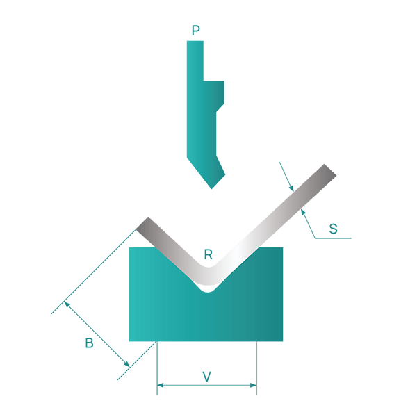
In air bending, the opening width V of the lower die is normally chosen to be 8 to 10 times the sheet thickness, S.
Press brake manufacturers usually list the corresponding values of the die width, V, and the inner diameter, r, of the bending part in their bending force parameter table.
As a general rule,
r=(0.16~0.17)V
However, when the inner radius is not equal to (0.16-0.17)V, the above calculation formula is no longer applicable.
In these cases, you must resort to a new calculation method to determine the required bending force or tonnage of the press brake.
Below is the calculator:
Pressure Brake Tonnage Table
The press brake tonnage table below can help you determine the required bending force with ease.
For instructions on how to read a press brake tonnage chart, see this post.
(1) Regular press brake tonnage table
V, R, B data
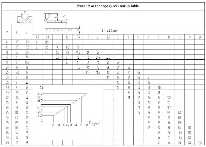
How to view press brake tonnage charts?
The tonnage indicated in the press brake tonnage table is based on a metal sheet with tensile strength of σb=450N/mm² and length of L=1m.
Now that you have the bending force chart, the next step is to understand how to locate the press brake tonnage on the chart.
Assuming your sheet metal is 4mm thick, the general rule is that the V-opening of the bottom die should be 8 times the thickness of the sheet.
However, when dealing with thicker sheets, a larger V-opening is required.
The recommended V-openings listed below can serve as a reference:
| s | 0.5-3mm | 3-8mm | 9-10mm | >12mm |
| V | 6*S | 8*S | 10*S | 12*S |
Let's consider a metal sheet with a thickness of 4mm.
Normally, the V-opening of the bottom die should be 8 times the sheet thickness. However, for thicker boards, the V-opening should be larger.
To determine the required press brake tonnage, we need to refer to the press brake tonnage table.
First, find the line with a thickness value of “4” and then determine the corresponding V-opening value of 32 (4 * 8).
The intersection of the line and column where the values “4” and “32” meet indicates a tonnage of 330 KN.
If we need to bend a 4mm sheet 3 meters long, the tonnage required would be 330 * 3 = 990 KN, or approximately 101 tons. In this case, we recommend choosing a press brake with a tonnage of at least 100 tons.
However, it is better to opt for a larger tonnage, such as 120 tons, as the machine's useful life will be longer if it operates at full load for long periods of time.
(2) Amada Press Brake Tonnage Table
(3) Hemming and seam tonnage table for mild steel and stainless steel
Hemming is a type of bending that requires a greater amount of tonnage compared to standard air bending.
The following tables illustrate the tonnage required for hemming and sewing operations.
(1) Hemming and stitching tonnage table for mild steel
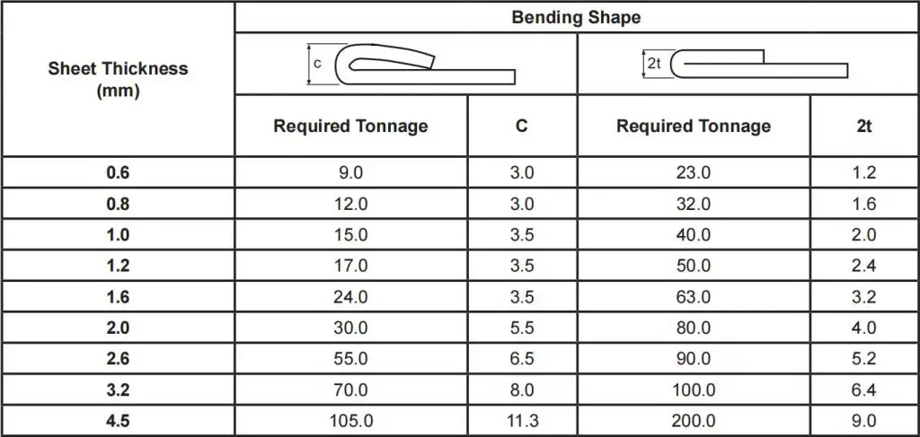
Note: The required tonnage is given per 1 meter of length
(2) Hemming and Seam Tonnage Table for Stainless Steel
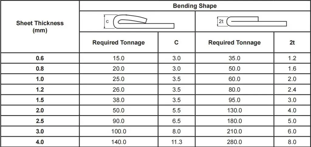
Note: The required tonnage is given per 1 meter of length
Press brake bend radius
During sheet metal bending, a bending radius at the bending point is required, which should not be too large or too small, but should be selected appropriately. If the bending radius is too small, it is easy to cause cracks at the bending point, while if the bending radius is too large, the bending may rebound.
(1) Bend radius table
The ideal bending radius (internal bending radius) for various materials of different thicknesses is shown in the table below.
Minimum value of the bending radius (mm)
| Materials science | Annealing state | Cold work hardening state | ||
| Corresponding position between the bending curve direction and the fiber direction | ||||
| vertical | parallel | vertical | parallel | |
| 08, 10 | 0.1t | 0.4t | 0.4t | 0.8t |
| 15, 20 | 0.1t | 0.5t | 0.5t | 1.0t |
| 25, 30 | 0.2t | 0.6t | 0.6t | 1.2t |
| 4550 | 0.5t | 1.0t | 1.0t | 1.7t |
| 65 minutes | 1.0t | 2.0t | 2.0t | 3.0t |
| Aluminum | 0.1t | 0.35t | 0.5t | 1.0t |
| Copper | 0.1t | 0.35t | 1.0t | 2.0t |
| Soft brass | 0.1t | 0.35t | 0.35t | 0.8t |
| Semi-hard brass | 0.1t | 0.35t | 0.5t | 1.2t |
| Phosphor bronze | / | / | 1.0t | 3.0t |
The data in the table above is great and for reference only. In fact, the manufacturer's bent blade roundness is usually 0.3, with some bent blades having a roundness of 0.5.
For common low-carbon steel plates, rust-proof aluminum plates, brass plates, copper plates, etc., an internal roundness of 0.2 is generally sufficient. However, for some high-carbon steels, hard aluminum, and super-hard aluminum, this type of flexural rounding can lead to flexural fractures or cracks in the outer rounding.
(2) Curvature radius calculation formula
Bent sheet metal parts require a bending radius r at the bend. Typically, designs for sheet metal parts have clear markings for the bend radius. The final size after bending is determined by the punch radius r 0 and the amount of springback △r, i.e.
r = r 0 + △r.
In actual production, the punch radius r0 used is predominantly between 0.3 and 0.5 mm, which can be considered a constant and has a minor impact on the radius of curvature and can often be disregarded. This means that the radius of curvature r is closely related to the springback △r.
However, the magnitude of springback is related to the bending pressure, which in turn is determined by the width of the die groove B and the thickness of the plate t. An increase in die groove width B reduces bending pressure and increases springback, while a decrease in B increases bending pressure and reduces springback.
Therefore, under certain conditions of the bending machine, the factors that most influence the bending radius are the punch radius r, the die groove width B and the sheet thickness t.
The following formula can be used to calculate the bending radius of the press brake:
Minimum inner border size
The minimum inside edge is the shortest side that can be bent without the sheet metal sliding into the V during bending.
In fact, the sheet metal must stay on both sides of the V while reaching the required angle, otherwise it will slide into the V, with subsequent unsatisfactory results.
The minimum internal edge can be calculated with the following formula:
If the required angle is 90°, minimum inner edge = V x 0.67
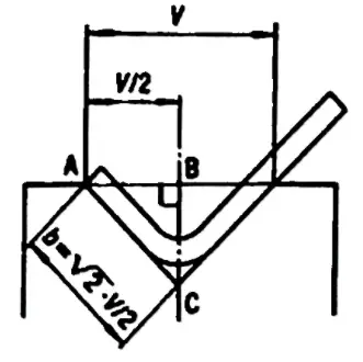
This formula derives from a geometric calculation, as the minimum internal edge is the diagonal of a square with side=V/2. So, taking into account the radius, the result is approximately V x 0.67.
When the required angle is different from 90°, the minimum internal edge will also be different, as the shortest side that can be in the V depends on the angle.
In fact, if a profile has an acute angle, the sheet metal will be pushed further into the die and therefore the side will have to be longer.
On the other hand, if a profile has an obtuse angle, a shorter side will be needed to rest on a die. For this reason, correction factors must be used to calculate the minimum suitable internal edge.
| Angle | Correction factors |
| 30° | B = (V x 0.67) x 1.6 |
| 60° | B = (V x 0.67) x 1.1 |
| 90° | B = (V x 0.67) x 1.0 |
| 120° | B = (V x 0.67) x 0.9 |
| 150° | B = (Vx 0.67) x 0.7 |
(1) Minimum bending edge calculation formula
The minimum bending edge calculation formula is different for different bending angles, which can be found in the table below.
| 165° | 135° | 120° | 90° | 60° | 45° | 30° |
| 0.51×V | 0.55×V | 0.58×V | 0.71×V | 1×V | 1.31×V | 1.94×V |
(2) Minimum bending height reference table
L-Bending
Reference table for internal bending radius R and minimum bending height of cold-rolled thin steel sheet materials:
| Serial number | Material thickness | Concave groove width | R Punch | Minimum bending height |
| 1 | 0.5 | 4 | 0.2 | 3 |
| two | 0.6 | 4 | 0.2 | 3.2 |
| 3 | 0.8 | 5 | 0.8/0.2 | 3.7 |
| 4 | 1.0 | 6 | 1/0.2 | 4.4 |
| 5 | 1.2 | 8 (or 6) | 1/0.2 | 5.5/4.5 |
| 6 | 1.5 | 10 (or 8) | 1/0.2 | 6.8/5.8 |
| 7 | 2.0 | 12 | 1.5/0.5 | 8.3 |
| 8 | 2.5 | 16(14) | 1.5/0.5 | 10.7/9.7 |
| 9 | 3.0 | 18 | 2/0.5 | 12.1 |
| 10 | 3.5 | 20 | two | 13.5 |
| 11 | 4.0 | 25 | 3 | 16.5 |
Z-fold
The minimum bending dimension L for bending Z of metal sheets with different thicknesses is shown in the table below:
Minimum z-curve height:
| Serial number | Material thickness | Concave groove width | R Punch | ZL curve height |
| 1 | 0.5 | 4 | 0.2 | 8.5 |
| two | 0.6 | 4 | 0.2 | 8.8 |
| 3 | 0.8 | 5 | 0.8/0.2 | 9.5 |
| 4 | 1.0 | 6 | 1/0.2 | 10.4 |
| 5 | 1.2 | 8(6) | 1/0.2 | 11.7(10.7) |
| 6 | 1.5 | 10(8) | 1/0.2 | 13.3(12.3) |
| 7 | 2.0 | 12 | 1.5/0.5 | 14.3 |
| 8 | 2.5 | 16(14) | 1.5/0.5 | 18.2(17.2) |
| 9 | 3.0 | 18 | 2/0.5 | 20.1 |
| 10 | 3.5 | 20 | two | 22 |
| 11 | 4.0 | 25 | 3 | 25.5 |
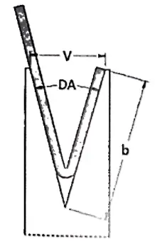
6. Flexion recovery
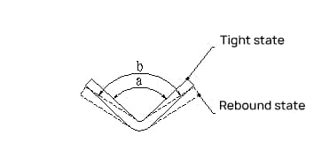
Flexion Recovery Angle:
Δα = b – a
where:
b – Actual angle of the part after the projection
a – Matrix angle
Rebound Angle Size:
Recovery angles for 90° single angle pneumatic bending are shown in the table below.
| Material | r/t | Thickness t(mm) |
||
| <0.8 | 0.8~2 | >2 | ||
| Low carbon steel | <1 | 4th | 2nd | 0° |
| Brass, σb=350MPa | 1~5 | 5th | 3rd | 1st |
| Aluminum, zinc | >5 | 6th | 4th | 2nd |
| Medium carbon steel, σb=400-500MPa | <1 | 5th | 2nd | 0° |
| Hard brass, σb=350-400MPa | 1~5 | 6th | 3rd | 1st |
| Hard copper, σb=350-400MPa | >5 | 8th | 5th | 3rd |
| High carbon steel, σb>550Mpa | <1 | 7th | 4th | 2nd |
| 1~5 | 9° | 5th | 3rd | |
| >5 | 12° | 7th | 6th | |
Factors affecting recovery and measures to reduce recovery:
- Material strength: The rebound angle is proportional to the yield point of the material and inversely proportional to its modulus of elasticity E. For sheet metal parts with high precision requirements, low carbon steel should be selected as much as possible to reduce rebound and high carbon steel, stainless steel, etc. should be avoided.
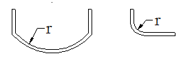
- Relative radius of curvature r/t: The greater the relative radius of curvature r/t, the smaller the deformation and the greater the rebound angle Δα. This is a very important concept. The bending radius of the metal sheet must be as small as possible, considering the performance of the material, which contributes to improving precision. Care must be taken to avoid designing large arches, such as the example shown below, which can cause difficulties in production and quality control.
When selecting tonnage for a bending machine, what factors need special consideration to ensure processing quality?
When choosing tonnage for a press brake machine, the following factors need special consideration to ensure processing quality:
Thickness and type of material: Firstly, it is crucial to ensure that the press brake can handle the thickness and type of material used.
Material and thickness of sheet metal required for processing: Calculating the required press brake tonnage based on the material and thickness of sheet metal required for processing is extremely important.
Bending radius of the workpiece: During the bending process, the bending radius of the workpiece is also a factor to be considered. This includes the use of free bending, where the radius of curvature is 0.156 times the size of the V-groove opening.
Bending accuracy: Lastly, you need to consider the bending accuracy, that is, choosing between a CNC bending machine or a manual bending machine, as this will directly affect the accuracy of the processed parts.