1. Brazing Characteristics
Brazing polycrystalline graphite and diamond materials faces similar challenges as ceramic brazing.
Compared to metals, brazing filler metals have difficulty wetting polycrystalline graphite and diamond materials, and their thermal expansion coefficients differ significantly from those of typical structural materials. If heated directly in air, oxidation or carbide formation may occur when the temperature exceeds 400°C.
Therefore, vacuum brazing must be adopted, with a vacuum level of no less than 10 -1 Pa. As polycrystalline graphite and diamond materials have low resistance, the presence of thermal stresses during brazing can lead to the formation of cracks.
It is important to select filler metals with a low coefficient of thermal expansion and strictly control the cooling rate.
Because the surface of such materials is not easily wetted by typical brazing filler metals, pre-brazing surface modification methods such as vacuum cladding, ion sputtering, or plasma spraying can be employed to deposit a layer of elements. like W and 2.5-12.5um thick. Mo on the surface of graphite and diamond polycrystalline materials, forming corresponding carbides, or high-activity brazing filler metals can be used.
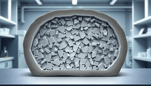
Graphite and diamond come in various grades, differing in particle size, density, purity and other aspects, and possessing different brazing characteristics.
Furthermore, for polycrystalline diamond materials in a vacuum environment, if the temperature exceeds 1000°C, the wear rate begins to decrease, and if it exceeds 1200°C, the wear rate decreases by more than 50%.
Therefore, in vacuum brazing of diamonds, the brazing temperature must be controlled below 1200°C, with a vacuum level of not less than 5×10 -2 Pai.
2. Selection of filler metal:
The selection of filler metal mainly depends on the application and surface processing conditions. When used as heat-resistant materials, brazing fillers with higher brazing temperature and good heat resistance should be chosen.
For materials with chemical corrosion resistance, brazing fillers with lower brazing temperature and good corrosion resistance should be selected. For graphite that has undergone surface metallization treatment, ductile and corrosion-resistant pure copper filler metals can be used.
Silver and copper-based active filler metals have good wetting and fluidity in both graphite and diamond, but the use temperature of the brazed joint should not exceed 400°C.
For graphite components and diamond tools used between 400 and 800°C, gold-based, palladium-based, manganese-based or titanium-based brazing fillers are typically used. For joints used between 800 and 1000°C, nickel or tungsten-based brazing fillers are chosen.
When graphite components are used above 1000°C, pure metal filler metals (Ni, Pd, Ti) or alloy filler metals containing elements such as molybdenum (Mo) or tantalum (Ta) can be used which can form carbides with carbon.
For graphite or diamond without surface treatment, the active brazing fillers listed in Table 16 can be used for direct brazing. These filler metals are mainly titanium-based binary or ternary alloys. Pure titanium reacts strongly with graphite, forming a thick layer of carbide, and its linear expansion coefficient differs significantly from graphite, leading to the formation of cracks.
Therefore, it cannot be used as a filler metal. Adding Cr and Ni to Ti can lower the melting point and improve wetting with ceramics. Ternary alloys based on Ti-Zr, with the addition of elements such as Ta and Nb, have a low coefficient of linear expansion, reducing brazing stresses.
Ternary alloys based mainly on Ti-Cu are suitable for brazing graphite and steel, providing high resistance to corrosion in joints.
Table 16: Filler metals for direct brazing of graphite and diamond.
| Welding material | Welding temperature (°C) |
Joint materials and fields of application |
| B-Ti50Ni50 | 960~1010 | Graphite-graphite, graphite-titanium, electrolytic cell terminal |
| B-Ti72Ni28 | 1000~1030 | |
| B-Ti93Ni7 | 1560 | Graphite-graphite, graphite-BeO, aerospace sector |
| B-Ti52Cr48 | 1420 | Graphite-graphite, graphite-titanium |
| B-Ag72Cu28Ti | 950 | Graphite-graphite, nuclear reactor |
| B-Cu80Ti10Sn10 | 1150 | Graphite Steel |
| B-Ti55Cu40Si5 | 950~1020 | Graphite-graphite, graphite-titanium, wear-resistant components |
| B-Ti45.5Cu48.5-A16 | 960~1040 | Graphite-graphite, graphite-titanium, wear-resistant components |
| B-Ti54Cr25V21 | 1550~1650 | Graphite refractory metals |
| B-Ti47.5Zr47.5Ta5 | 1600~2100 | Graphite-graphite |
| B-Ti47.5Zr47.5Nb5 | 1600~1700 | Graphite-graphite, graphite-molybdenum |
| B-Ti43Zr42Gel5 | 1300~1600 | Graphite-graphite |
| B-Ni36-40 Ti5~10 Fe50~59 |
1300~1400 | Graphite-molybdenum, graphite-silicon carbide, heating elements |
3. Brazing Process
Graphite brazing methods can be divided into two categories: one is brazing after surface metallization, and the other is brazing without surface treatment. Regardless of the method used, before assembling the welded parts, the parts must be pretreated by wiping the surface of the graphite material with alcohol or acetone to remove any contaminants.
When using surface metallization brazing, a layer of Ni or Cu can be electroplated onto the graphite surface, or a layer of Ti, Zr, or molybdenum disilicide can be deposited using plasma spraying.
Then copper or silver based brazing materials are used for the brazing process. The most commonly employed method is direct brazing using active brazing materials, and the brazing temperature can be selected based on the brazing materials given in Table 16.
The brazing material can be placed in the middle or near one end of the welded joint. When brazing with metals that have a high coefficient of thermal expansion, a certain thickness of Mo or Ti can be used as an intermediate buffer layer.
This transition layer can undergo plastic deformation during heating, absorbing thermal stress and preventing cracking of the graphite.
For example, for vacuum brazing of corrosion-resistant nickel-based Hastelloy N components and graphite, a brazing material B-Pd60Ni35Cr5 with good resistance to molten salt corrosion and radiation resistance is used. The brazing temperature is 1260°C and the insulation time is 10 minutes.
Natural diamond can be directly brazed using active brazing materials such as B-Ag68.8Cu16.7Ti4.5 and B-Ag66Cu26Ti8. Brazing must be carried out under vacuum or protection with low argon gas content. The brazing temperature should not exceed 850°C and a faster heating rate should be selected.
The residence time at the brazing temperature should not be too long (generally around 10 seconds) to avoid the formation of a continuous TiC layer at the interface.
When brazing diamonds into alloy steel, a plastic interlayer or a low-expansion alloy layer should be used as a transition to avoid excessive thermal stress that can damage the diamond grains.
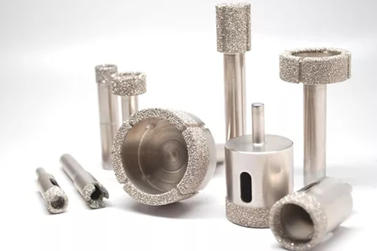
Brazing processes are used to manufacture ultra-precision machining tools such as turning tools or boring tools by brazing small diamond particles (20-100mg) onto a steel body. The strength of the welded joint reaches 200-250MPa.
Polycrystalline diamond can be brazed using flame brazing, high frequency brazing or vacuum brazing. Diamond circular saw blades used for cutting metal or stone must be welded using high frequency brazing or flame brazing with low melting point active brazing materials such as Ag-Cu-Ti.
The brazing temperature should be controlled below 850°C and the heating time should not be too long. Slow cooling must be adopted. For polycrystalline diamond bits used in geological and petroleum drilling, which are subject to harsh working conditions and significant impact loads, nickel-based brazing materials can be selected and pure copper foil can be used as the intermediate layer for brazing in vacuum.
For example, to braze 350-400 cylindrical polycrystalline diamond particles (4.5-4.5 mm) into the holes of 35CrMo or 40CrNiMo steel teeth to form cutting teeth, vacuum brazing is employed with a degree of vacuum not less than at 5×10⁻²Pa. The brazing temperature is 1020±5°C, the insulation time is 20±2 minutes, and the shear strength of the welded seam is greater than 200MPa.
During brazing, it is advisable to use the weight of the part for assembly and positioning, allowing the metal parts to press against the graphite or polycrystalline material. When using fixtures for positioning, the material of the fixtures should have a similar coefficient of thermal expansion to that of the part.
Brazing of aluminum-based composite materials (1) Brazing characteristics Aluminum-based composite materials are mainly classified into two categories: particle-reinforced (including whiskers) and fiber-reinforced, with materials such as B, CB, SiC used for reinforcement.
During heating of aluminum-based composite materials for brazing, the base Al easily undergoes chemical reactions with the reinforcing phase. For example, Si in the brazing material quickly diffuses into the base material, leading to the formation of a layer of brittle droplets. This reduces the performance of the material.
Furthermore, due to the significant difference in the coefficient of linear expansion between the Al and the reinforcing phase, inadequate brazing heating can generate thermal stress at the interface, leading to cracking of the joint.
Furthermore, there is poor wettability between the brazing material and the reinforcement phase, necessitating surface treatment of the brazing composite material or the use of active brazing materials. Vacuum brazing should be adopted whenever possible.
(2) Brazing Materials and Process
Aluminum-based composite materials reinforced with B particles or SiC can be brazed using soft brazing techniques. Before brazing, surface treatment can be carried out by polishing with sandpaper, steel brushing, alkaline washing or electrolytic nickel plating (coating thickness 0.05 mm).
Brazing materials such as S-Cd95Ag, S-Zn95Al and S-Cd83Zn can be used, with gentle heating by oxy-acetylene flame. Furthermore, the use of S-Zn95Al brazing material for friction brazing can achieve high joint strength.
Vacuum brazing can be applied to join short fiber reinforced 6061 aluminum-based composite materials. The surface must be sanded and polished with 800 grit sandpaper before being ultrasonic cleaned with acetone.
Al-Si brazing materials are mainly used, and to prevent the diffusion of Si into the base material, a barrier layer of pure aluminum foil can be coated on the brazing surface of the composite material.
Alternatively, a brazing material B-Al64SiMgBi (11.65i-15Mg-0.5Bi) with lower brazing resistance can be chosen. The melting temperature range of this brazing material is 554-572°C, and the brazing temperature can be selected as 580-590°C with a brazing time of 5 minutes. The shear strength of the joint is more than 80MPa.
For aluminum-based composite materials with graphite particle reinforcement, vacuum brazing in a furnace with a protective atmosphere is the most successful method. To improve wettability, Al-Si brazing materials containing Mg should be used.
Similar to vacuum brazing of aluminum, the introduction of Mg vapor or Ti outgassing, as well as the addition of a certain amount of Mg, can significantly improve the wettability of the brazing material for aluminum-based composite materials.
Weldability of various materials
| Materials | Weldability | Welding material | Flow | Observation | ||
| Hard welding | Soft welding | |||||
| Carbon steel, low alloy structural steel | Great | Great | HL-104 copper-zinc solder
Brass Silver-based solder Tin-lead solder |
Borax or a mixture of borax and boric acid
Welding with borax or shielding gas JO102 JO104 Zinc chloride or a mixture of zinc chloride and ammonium chloride |
||
| Carbon steel for tools | Good | – | HL-104
Brass Silver-based solder |
Borax or a mixture of borax and boric acid
Borax or shielding gas solder JO102 JO104 |
||
| High speed steel and carbon steel | Good | – | High carbon manganese steel | Borax | ||
| Hard league | Good | – | HL-104
HL-301 |
Borax or a mixture of borax and boric acid
OJ 102 |
||
| Cast iron | Good | – | HL-104
Silver-based solder |
Borax or a mixture of borax and boric acid
OJ 102 |
||
| Stainless steel | 1Cr18Ni9Ti (stainless steel) | Good | Good | Copper-nickel solder
Copper Silver-based solder Nickel-based solder Manganese-based solder Tin-lead solder |
OJ 104
OJ104, gas shielded welding JO102, JO104 Grade 201, gas shielded or vacuum brazed Brazing with gas or vacuum protection Phosphoric acid solution, zinc chloride hydrochloric acid solution |
|
| Stainless steel | 1Cr3 (stainless steel) | Good | – | Copper-nickel solder
CopperSilver based solder Nickel-based solder Manganese-based solder Tin-lead solder |
OJ104OJ104, gas shielded welding
JO102, JO104 Grade 201, gas shielded or vacuum brazed Brazing with gas or vacuum protection Phosphoric acid solution, zinc chloride hydrochloric acid solution |
|
| High temperature alloy | Good | – | Silver-based solder
Copper Nickel-based solder |
OJ 102
Brazing with gas or vacuum protection Brazing with gas or vacuum protection |
||
| Silver | Great | Great | Silver-based solder
Tin-lead solder |
JO102, JO104
Rosin alcohol solution |
||
| Copper, brass, bronze | Great | Great | Copper-phosphorus solder
Copper-zinc solderSilver-based solder Cadmium-based solder Lead-based solder Tin-lead solder |
No flux is required for copper soldering. For copper alloys, borax or a mixture of borax and boric acid can be used as a flux.
Borax or a mixture of borax and boric acid JO102 JO104 OJ 205 Zinc chloride solution Rosin alcohol solution, zinc chloride or zinc chloride-ammonium chloride solution |
||
| Aluminum and aluminum alloys | L2, LF21 (aluminum alloys) | Great | Great | Aluminum-based solder
Zinc-tin solder HJ501 Zinc-cadmium welding HJ502 HJ607 Aluminum Soft Weld HJ607 Aluminum Soft Weld Aluminum Welding Plate |
OJ 201, OJ 206
Scraper method OJ 203 OJ 204 OJ 202 Flux No.1, No.2 for dip welding |
No flux is required for vacuum brazing. |
| Aluminum and aluminum alloys | LF1, LF1-2 (aluminum alloys) | Good | Good | |||
| Aluminum and aluminum alloys | LF5, LF6 (aluminum alloys) | Poor | Poor | |||
| Aluminum and aluminum alloys | LD2 (aluminum alloys) | Good | – | Aluminum-based solder | OJ 201, OJ 206 | Be careful to avoid overheating |
| Aluminum and aluminum alloys | LD5, LD6 (aluminum alloys) | Difficult | – | HL402 aluminum-based welding | No.1 and No.2 flux for dip welding | Prone to overheating, it is recommended to use dip welding |
| Aluminum and aluminum alloys | LY12, LC4 (aluminum alloys) | Poor | – | Very prone to overheating, not suitable for welding | ||
| Cast aluminum alloys | Al-Cu series (aluminum-copper alloys) | Difficult | – | HL505 | OJ 202 | Tends to overheat easily |
| Cast aluminum alloys | Al-Si series (aluminum-silicon alloys) | Difficult | – | HL401, HL505 | OJ 201, OJ 202 | Poor moistening |
| Cast aluminum alloys | Al-Mg series (aluminum-magnesium alloys) | Poor | – | Difficult to remove surface oxides, difficult to weld | ||
| Cast aluminum alloys | Al-Zn series (aluminum-zinc alloys) | Good | – | Aluminum-based solder | OJ 201, OJ 206 | |
| Cast aluminum alloys | Die Cast Parts | Poor | – | Bubbling on the surface of the base material | ||
| Titanium and titanium alloys | Good | – | Ag-5Al-0.5Mn
Ti-15Cu-15Ni |
Brazing with vacuum or gas protection | Lower joint ductility | |
| Diamond and steel | – | – | HL104 | Borax | Be careful to avoid cracking | |
| Aluminum and copper | – | – | 90Sn-10Zn
99Zn-1Pb |
Alternatively, the aluminum surface can be coated with copper before welding. | Alternatively, the aluminum surface can be coated with copper before welding. | |
| Titanium and steel, titanium and stainless steel | – | – | HL308
Ag-5Al-0.5Mn |
Brazing with vacuum or gas protection | The joint is relatively fragile | |
| Aluminum and iron | – | Great | HL502
90Sn-10Zn |
OJ 205
OJ 203 |
Alternatively, the aluminum surface can be coated with copper before welding. | |
| Ceramic-ceramic, ceramic-metal | – | – | 72Ag-28Cu+Ti Powder | Brazing with vacuum or gas protection | Or, after metallizing the ceramic surface, welding can be carried out | |
| Graphite | – | – | Powder 72Ag-28Cu+Ti,
Ti-Cu, Ti-Ni |
Brazing with vacuum or gas protection | ||