INJECTION MOLDING PROCESS
Injection molding is the most widely used polymer manufacturing process. It evolved from metal die casting, however, unlike molten metals, molten polymers have a high viscosity and cannot simply be poured into a mold. Instead, great force must be used to inject the polymer into the hollow mold cavity. More molten material must also be placed into the mold during solidification to prevent mold shrinkage. The injection molding process is primarily a sequential operation that results in the transformation of plastic pellets into a molded part. Identical parts are produced through a cyclic process that involves melting a pellet or powdered resin followed by injecting the molten polymer into the hollow mold cavity under high pressure.
INJECTION MOLDING MACHINE
An injection molding machine produces components by injection molding process. The most commonly used machines are hydraulically driven in-line screw machines, although electric machines are emerging and will be more dominant in the market in the near future.
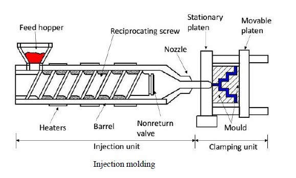
The main units of a typical injection molding machine are the clamping unit, the plasticizing unit and the drive unit; they are shown in Fig. The clamping unit holds the mold. It is capable of closing, fixing and opening the mold. Its main components are the fixed and movable plates, the tie rods and the opening, closing and fixing mechanism.
The injection unit or plasticizing unit melts the plastic and injects it into the mold. The drive unit supplies power to the plasticizing unit and the clamping unit.
Injection molding machines are often rated by the maximum clamping force the machine can generate. This is the force that pushes the two halves of the mold
together to prevent the mold from opening due to the internal pressure of the molten plastic in the mold. The clamping force of typical injection molding machines
range from 200 to 100,000 kN.
There are several types of injection machines, and the difference lies in the way these two devices are arranged.
(1)Horizontal injection molding machine : Horizontally compound mold clamping device and injection device
(2) Vertical injection machine: Vertically compound mold clamping device and injection device
(3) Two color injection molding machine
(4) Rotary injection molding machine
(5)Low foam injection machine
(6) Multi-material injection molding machine
(7) Sandwich injection molding machine
THE INJECTION MOLDING CYCLE – Operation
 injection molding diagram
There are three main steps in the injection molding cycle;
step 1, injection, followed by step 2, pressure retention and plasticization and, finally, step 3, ejection of the molded part. When step 3 is complete, the mold closes again and the cycle begins again.
Step 1- INJECTION OF THE PLASTIC HOLE INTO THE MOLD:
In step 1, the mold is closed and the extruder nozzle is pushed against the mold sprue bushing. The screw, without turning at this point, is pushed forward so that the molten plastic in front of the screw is forced into the mold.
Step 2- HOLDING PRESSURE AND PLASTIFICATION:
When the mold is completely filled, the screw remains stationary for some time to keep the plastic in the mold under pressure, this is called “holding” time. During the holding time, additional molten material is injected into the mold to compensate for shrinkage due to cooling. Later, the gate, which is the narrow entrance to the mold, freezes. At this point the mold is isolated from the injection unit. However, the melt inside the mold is still at high pressure. As the casting cools and solidifies, the pressure must be high enough to avoid sink marks, but low enough to allow easy removal of the parts.
During the plasticization phase, material is pushed from the feed hopper through the cylinder and toward the nozzle by a rotating screw. When the gate freezes, the screw rotation starts. The period of rotation of the screw is called “recovery” of the screw. The rotation of the screw causes the plastic to be transported forward. As the plastic advances, heat from the electric heater spreads along the cylinder and the shear begins to melt the plastic. At the discharge end of the screw, the plastic will be completely melted. The melt that builds up on the end of the screw pushes the screw back. Thus, the screw rotates and moves backwards at the same time. The rate at which molten plastic accumulates in front of the screw can be controlled by screw backpressure, i.e., the hydraulic pressure exerted on the screw. This also controls the melt pressure in front of the screw.
When enough molten mass is accumulated in front of the screw, the screw rotation stops. During screw recovery, the plastic in the mold is cooled, but typically the cooling does not end at the end of screw recovery. As a result, the screw will remain stationary for some period until cooling is complete. This period is often referred to as “immersion” time. During this time, additional plastic will melt in the extruder due to conductive heating. Furthermore, the melted material
achieve more thermal uniformity, although the immersion time is generally too short to
significantly improve thermal homogeneity.
EJECTION Stage 3:
When the material in the mold has cooled enough to hold its shape, the mold opens and the parts are ejected from the mold, as shown in the figure.
When the molded part is ejected, the mold closes and the cycle begins again.
The different stages can be illustrated graphically as shown in Fig. The top bar shows the movement of the extrusion screw, the second bar shows the action that occurs inside the mold and the third bar indicates when the mold is open and closed.
 injection molding cycle time
As can be seen in Fig., the majority of the injection molding cycle is the cooling time required for the plastic in the mold to reduce to a temperature where the part can be removed without significant distortion. The main variable that determines cooling time is the thickness of the molded part.