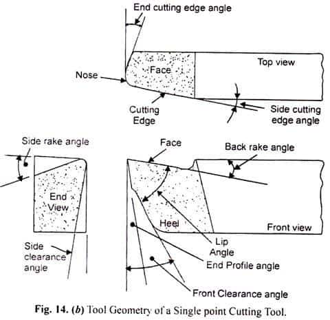
The face and flank are pain surfaces, the cutting edge can be assumed as a line. These surfaces and edges are inclined with respect to some plane or reference line. The slopes are called tool angles.
These angles are defined by various names. They are provided for various purposes. Consider the case of face abgf, as shown in Fig. It is a flat surface without a doubt, but it may have some slopes. This surface may be parallel to the base or, say, the horizontal surface, or it may be inclined up or down with respect to the horizontal plane. Again, it can also be tilted sideways. Thus, in general, the face can have two inclinations simultaneously, backwards and sideways. Likewise, the flank (abed main flank or adef auxiliary flank) can have two slopes.
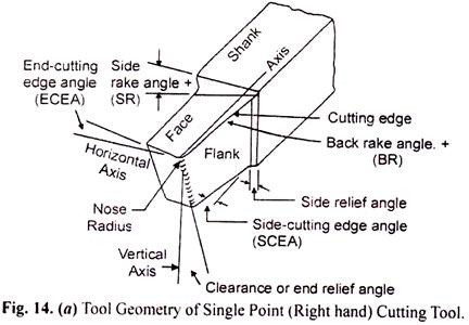
 single point cutting tool geometry 2
From the geometry of the cutting tool, the various angles of the cutting tool are:
Tilt angle (α):
(a) Black tilt angle.
(b) Side inclination angle.
Angle of Clearance or Relief (γ):
(a) End gap relief angle.
(b) Side play relief angle.
Cutting angle:
(a) Angle of the final cutting edge.
(b) Side cutting edge angle.
(i) Rear lean angle:
It is the angle between the face of the tool and the plane parallel to its base. It is also known as forward lean angle or top lean angle.
(ii) Side inclination angle:
It is the angle between the tool face and the tool shank.
(iii) Final clearance angle (relief):
It is the angle between the front surface of the tool and a line normal to the base of the tool. It is also known as the frontal incidence angle.
(4) Side clearance (relief) angle:
It is the angle between the side surface of the tool and a line normal to the base of the tool.
(v) End cutting edge angle:
It is the angle between the final cutting edge of the tool and a line perpendicular to its shank.
(vi) Side cutting edge angle:
It is the angle between the side cutting edge of the tool and the tool shank.
(vii) Nose ray:
The nose radius is the one that connects the side and end cutting edge.
Now, we will discuss the functions and effects of cutting tool angles in the cutting process.
Back tilt angle functions:
(a) It helps to control the flow of chips in a convenient direction.
(b) Reduces the cutting force required to shear the metal and consequently helps reduce power requirements and increase tool life.
(c) It also helps to neutralize the pressure of the work against the cutting tool by pulling the tool into the work.
(d) Provides sharpness to the cutting edge and improves surface finish.
Side Tilt Angle Functions:
(a) It performs similar functions to those performed by the back tilt angle.
(b) The side rake angle, together with the back rake angle, controls the direction of chip flow.
(c) Partially neutralizes the resistance of the part to the movement of the cutter.
(d) For example, brass requires a side and back slope angle of almost 0°, while aluminum uses a 35° back slope and a 15° side slope.
Functions of the final clearance angle (relief):
(a) Allows the tool to cut freely without friction with the work surface.
(b) This angle varies from 0° to 15°, and generally 8°.
(c) Excessive relief angle reduces tool strength.
Functions of the side clearance angle (relief):
I. Prevents flank friction against the workpiece when the tool is fed longitudinally.
ii. This angle is 6° to 10° for steel, 8° for aluminum.
iii. It states that no part of the tool, other than the cutting edge itself, can touch the part.
End cutting edge angle functions:
i. Prevents friction between the edge of the tool and the work area.
ii. Influences the direction of chip flow.
Side cutting edge angle functions:
i. Increasing the angle of the side cutting edge tends to widen and thin the chip.
ii. An excessive side cutting edge angle redirects feed forces in the radial direction, which can cause chatter.
Nose ray functions:
I. A sharp point at the end of the tool is undesirable because it is highly stressed, short-lived, and leaves grooves in the cutting path.
ii. Therefore, the Tip Radius is favorable for long tool life and good surface quality.
iii. It affects the tool life, radial force and surface quality of the workpiece.
iv. If the nose radius is too large, vibration will occur.
v. There is an ideal value of the nose radius at which tool life is maximum.
saw. If the tip radius exceeds the ideal value, tool life decreases.
viii. Larger tip radius means larger contact area between tool and workpiece. Resulting in more frictional heat generated. Additionally, the cutting force increases, which can cause the workpiece to start vibrating and shaking if the workpiece is not clamped very firmly.
viii. Recommendations for using a larger tip radius are:
R= 0.4 mm for delicate components.
R = 0.4mm to 1.2mm for common use disposable carbide inserts.
R = 1.2mm to 1.5mm for heavy duty inserts.
R ≥ 1.5 mm for high cutting depth, interrupted cuts and intense feeds.
Tilt angle meaning:
1. Tilt angles can be positive, zero or negative.
2. An increased rake angle will reduce cutting edge strength.
3. The angle of attack affects the cutting angle and shear angle values.
4. The greater the angle of attack, the smaller the cutting angle (and the greater the shear angle).
5. In general, small rake angle is used for cutting hard metals and larger rake angle is used for cutting soft and ductile metals.
6. The use of negative rake angle began with the use of carbide cutting tools. When a positive rake angle is used, the force on the tool is directed towards the cutting edge, tending to chip or break it, as shown in Fig.
7. Because carbide material is brittle and has no shock resistance, it will fail if positive rake angles are used with it. Using negative rake angles directs the force back into the tool body, away from the cutting edge, which protects the cutting edge, as shown in Fig.
 single point cutting tool geometry
8. Using negative rake angle increases cutting force. This can be compensated by higher cutting speeds. Therefore, high cutting speeds are always used with negative rake angles. High cutting speeds require high machine tool power.
9. The use of indexable inserts also requires the use of negative rake angles.
10. An insert with a negative rake angle has twice the life of an insert with an equivalent positive rake angle.
11. The negative rake angle increases the strength of the cutting edge, because the cutting force acts in the middle of the cutting edge.
12. Positive rake angle decreases cutting edge resistance because the cutting force acts at the end or corner of the cutting edge.
13. Positive tilt angle recommendations are:
(a) When machining low strength metals and alloys such as aluminum and copper alloys, mild steel, etc.
(b) When cutting at low speeds.
(c) When installed, it has low strength and rigidity.
(d) When low power machines are used.
(e) When tool materials are HSS and cast alloys.
14. Negative tilt angle recommendations are:
(a) When machining high-strength metals and alloys such as stainless steel, tool steel alloys, titanium alloys, etc.