A plate rolling machine is a universal forming equipment that rolls sheet metal into cylindrical, arc and other general shapes.
It is widely used in industries such as boilers, shipbuilding, petroleum, chemicals, metal structures and mechanical manufacturing.
The four-roll sheet metal bending machine is known for its convenient center alignment, small amount of excess straight edge, high accuracy in correcting roundness and efficiency as it can complete pre-bending and part forming in a single rolling process without the need to change the end of the board.
It is becoming increasingly important in sheet metal forming.
Roll bending force conditions during four-roll sheet metal bending operation are complex and involve significant load, requiring strong and rigid bearing parts.
Therefore, accurate and reliable design of plate rolls is essential.
To begin with, the force parameters of the roll bending machine need to be determined, such as roll pressure, bending torque and motor power.
Rolling mill load analysis can serve as reference data for sheet roll design.
Calculating the main driven power of the sheet metal bending machine is crucial when choosing the main engine.
Motor power must be selected carefully, as a motor that is too small will be overloaded for long periods and damaged due to heat from the insulation, while a motor that is too large will not fully utilize its power output and will waste electricity.
Therefore, carrying out a load analysis and improving the calculation of the driven power of the four-roll sheet metal bending machine has practical value in choosing a suitable engine.
In this post, we not only introduce the basic structure and working principle of the four-roll sheet metal bending machine, but also analyze its strength capabilities and provide the calculation formula for the main driven power of the four-roll sheet metal bending machine.
Structure and working principle of four-roll bending machine
The rolling mill operates based on the principle of three-point forming, utilizing the relative position change and rotational movement of the work roll to produce continuous elastoplastic bending and achieve the desired shape and precision of the workpiece.
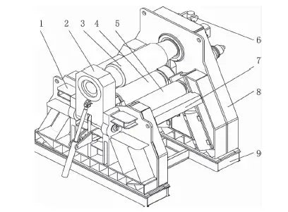
The structure of the four-roll sheet metal bending machine is shown in Figure 1 and is composed of several parts, including a low frame, tipping device, upper roller, lower roller, two side rollers, high frame, connecting beam, base, device balancing system, transmission device, electrical system and hydraulic system.
The work roller of the four-roll plate machine consists of four rollers: an upper roller, a lower roller and two side rollers.
The upper roller is the main driving roller and is embedded in the high and low frame through a bearing body. Its position is fixed, allowing only rotational movements.
The lower roller is fixed on a bearing pedestal, which can move in a straight line to compensate for the thickness of the bent plate.
The two side rollers are also installed on bearing pedestals, which can move up and down at a certain angle with the vertical direction to achieve the desired cylinder curvature radius.
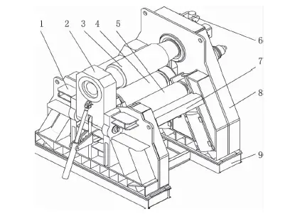
Fig.1 Structure of four-roll sheet metal bending machine
- 1. left frame
- 2. drop the device
- 3. top roller
- 4. bottom roller
- 5. side roll
- 6. balancing device
- 7. connecting beam
- 8. right frame
- 9. base
In general, rolling a sheet metal into a cylindrical part on a four-roll bending machine consists of four processes, namely:
- Center alignment
- Pre-bending
- Rolling
- Rounding correction
During rolling mill operation, the front end of the plate is placed between the upper and lower rollers and aligned with one of the side rollers. The bottom roller is then lifted to firmly press the plate, and the other side roller is lifted to apply force and bend the end of the metal plate.
To pre-bend the other end of the board, it does not need to be removed from the laminator. Simply move the plate to the other end of the machine and repeat the process.
Continuous rolling is achieved through single or multiple feeding until the desired radius of curvature of the cylinder is achieved.
Finally, roundness corrections are made to achieve the required roundness and cylindricity.
It can be seen that the use of the four-roll plate calender allows the plate to be placed in the machine only once, achieving all the necessary bending.
Load Analysis
2.1 Calculation of the maximum bending moment of the plate
As shown in FIG. 2, the stress distribution of the plate section along the height direction of the steel plate during linear bending of pure plastic is shown in FIG. two.
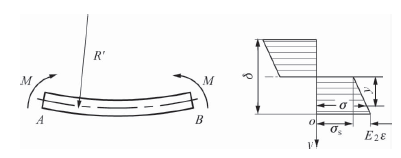
Fig.2 Plate stress distribution
The true voltage functional relationship can be expressed as follows:
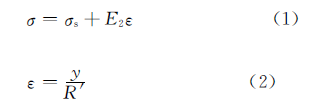
In the formula above:
- σ – the tension of the part;
- σ is – the yield limit of the material;
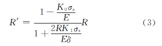
- ε – the deformation of the part;
- ε – The linear reinforcement module of the material can be consulted in the respective manual.
- y- The distance from the neutral axis to any point;
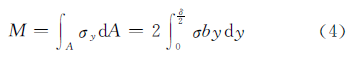
- R′ – The radius of curvature before rebound of the neutral layer can be calculated as follows:
In the formula above:
- R – Rolling radius;
- δ – Thickness of the rolled steel sheet;
- E- Modulus of elasticity of the steel sheet;
- K 0 – The relative modulus of resistance of the material can be consulted in the relevant manual.
- K 1 – Shape coefficient, rectangular cross sectionK1=1.5
The bending moment in the cross section M is:
Putting the formula (1) and (2) into (4), we obtain:
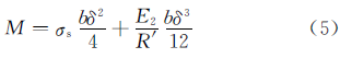
In the formula above: b – The maximum width of the rolled steel sheet.
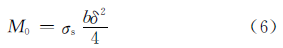
Initial deformation bending momentM0 is:
2.2 Calculation of working bearing force
The structural characteristics of the four rollers allow for two different arrangements: a symmetrical arrangement and an asymmetrical arrangement.
Therefore, a separate force analysis of the four-roller machine is required.
2.2.1 The rollers are arranged symmetrically
The strength of the steel plate is shown in FIG. 3.
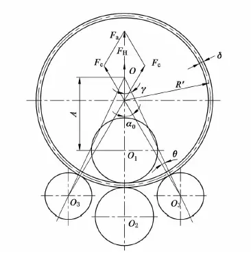
Fig.3 Effect of force under symmetrically arranged roller
According to the balance of forces, the force of each work roller on the steel plate can be obtained:
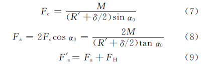
In the formula above:
- F H – Lower roller output hydraulic force;
- F c – Lateral rolling force;
- F a – Rolling deformation force of the upper roller plate.
- F a – Total force of the upper roller;
- α 0 – The angle between the side roller's line of force action and the upper roller's line of force.
The value of α 0 can be determined by the following formula according to the geometric relationship:
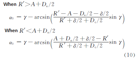
In the formula above:
- D a – Upper diameter of the roll;
- D c – Diameter of the side roller;
- γ – Side roll inclination angle, which is the angle between the side roll adjustment direction and the vertical direction;
- A – The distance from the point of intersection of the rolling angle to the center of the upper roller.
2.2.2 The rollers are arranged asymmetrically
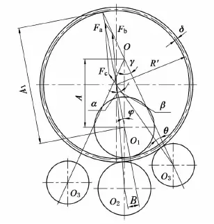
The strength of the steel plate is shown in FIG. 4 when the roll is arranged asymmetrically.
According to the balance of forces, the force of each work roller on the steel plate can be obtained:
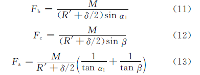
In the formula above:
- F b – Lower rolling force;
- α – The angle between the line of force action of the upper roller and the line of force of the lower roller;
- β – The angle between the line of force action of the upper roll and the line of force of the side roll.
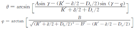
The value of α, β can be determined by the following formula according to the geometric relationship:
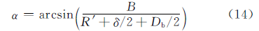
In the formula above:
- D b – Lower diameter of the roll;
- B – The distance between the line of action of the upper roller and the center of the lower roller,
- B= (1+D b /(2R'+δ)B';
- B' – The length of the remaining straight edge, B'=2δ
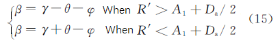
In the formula: A 1 = Asinγ/sin(γ – φ)
Driven power calculation
3.1 Upper roller drive torque
The upper roller of the four-roll bending machine is a driven roller, and the total driving torque acting on it is the sum of the torque consumed by deformation and friction.
Frictional torque includes the frictional resistance consumed by rolling the shaft roller on the bending plate and the torque consumed by bearing friction.
The torque consumed in deformation can be determined by the work done by the internal bending force and the external force on the upper roller.
In the formula:
- C n – The work done by internal bending forces;
- C c – The work on the upper roller by external forces;
- L – The bending angle corresponds to the length of the plate.
Making formula (17) equal to formula (18), we obtain the torque consumed in the deformation:
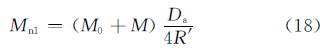
The torque to overcome friction can be determined by formulas (19) and (20).
Shaft roller friction torque in symmetrical arrangement:
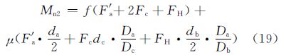
Shaft roller friction torque in asymmetrical arrangement:
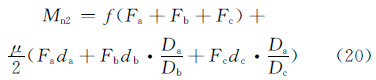
In the formula above:
- f – Rolling friction coefficient, f =0.8mm
- μ – Roller neck sliding friction coefficient, μ=0.05-0.1;
- d a, d b, d c are the neck diameter of upper roller, lower roller and side roller separately.
The total drive torque on the upper roller is:
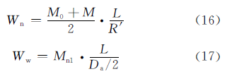
3.2 Upper roller drive power
The formula for calculating driving power is:
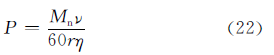
In the formula:
- ν – Rolling speed;
- r – Radius of the driven roller, r=D to /2
- η – Transmission efficiency, η=0.9
According to the actual application condition of the four-roll sheet metal bending machine, the driving power of the driving roll is calculated during the pre-bending and rolling process, and the driving power of the main drive system is the largest value in the result of the calculation:
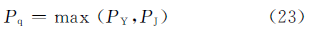
In the formula above:
- P q – Motive power of the main drive system;
- P S – The driving power of the driving roll during pre-bending;
- P J. – The driving force of the driving roller when rolling the circle.
The calculated value P q of the motive power can be used as a basis for selecting the main engine power.
Conclusion
(1) Based on the structural characteristics and working principle of the four-roll plate bending machine, the force of the work roll is analyzed and the formula for calculating the work roll under different arrangements is obtained.
(2) By analyzing the maximum deformation bending moment and rolling force of the work roller and using the principles of function transformation, the relationship between force, bending moment and driving power of the device is established. A method for calculating the motive power of the main drive system is proposed.
According to the actual application conditions, the driving power for pre-bending and rolling is calculated separately, and the power of the main motor is selected based on the largest calculated value.