To increase the bending accuracy of elevator sheet metal components, the bending radius (R-angle) of commonly used materials such as SPC, SPHC, SUS304 and 804-GG was accurately measured at a 90° angle using a CNC press brake in sheet metal workshop. An optical measuring instrument was used to determine the radius of curvature and the coefficient of curvature was calculated using calipers.
The test results serve as a reference and provide data support for the selection of appropriate bending tools, increasing the accuracy of the R angle during bending and improving the accuracy of calculating bend dimensions.
Significance of the test
The bending radius (within R) and the bending coefficient are crucial factors that impact the quality of the bending process. The bending radius is associated with the bending tool, material thickness and performance factors, while the bending coefficient is determined by the material thickness, bending radius and bending angle. The bending coefficient also affects the unfolded dimensions of the part.
The current formula for calculating the 90° bending factor is α = 1.36t + 0.43R (where t represents the thickness of the material plate). Some of the common errors in bending factor calculation include:
- The difference between the value and the actual thickness of the material.
- The deviation between the actual bending within R and the required internal bending as indicated on the drawing (within R is usually taken from the drawing when calculating α).
- The use of R gauge measurement (where R gauge values below R3 are 0.25 and above R3 are 0.5) in determining R flexure, which results in lower accuracy.
- The influence of material and bending method on bending R is not taken into account.
When a part is bent multiple times, the error in the bending coefficient accumulates, leading to poor dimensional accuracy in the finished product.
To solve these problems, this experiment measured the actual thickness of various bending materials, used an optical measuring instrument to more accurately determine the internal and external bending radius, calculated the actual curvature coefficient of the part, and compared the results with the formula. This will help in selecting appropriate bending dies, improve the accuracy of bending forming R, and expand the accuracy of dimensional calculations.
Test scheme
Test material
The test materials used in the experiment were SPCC, SPHC, SUS304 and 804-GG, which were purchased by our company. Thickness specifications for each material can be found in Table 1.
Table 1 Test materials and thickness (mm)
|
Thickness t/mm |
1.0 | 1.2 | 1.5 | 2.0 | 2.3 | 2.5 | 3.0 | 3.2 | 4.5 | 6.0 |
| SPCC | √ | √ | √ | √ | √ | √ | ||||
| SPHC | √ | √ | √ | |||||||
| SUS304 | √ | √ | √ | √ | √ | |||||
| 804-GG | √ |
Test sample
The size of the samples used in the experiment was 100mm x 100mm and were produced by laser cutting and blanking. This ensured that the dimensional accuracy of the samples was at the level of 0.1 mm.
Test Equipment
The test bending machine used in the experiment was a CNC bending machine located in the elevator sheet metal production workshop. The V-groove used in the experiment featured FASTI-50 and Beyeler, and the upper scimitar die was selected, as illustrated in Figure 1.
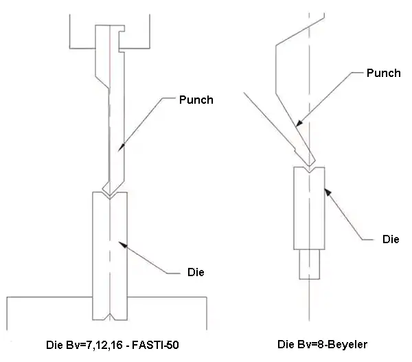
Fig.1 V-groove bending die
The three-point press brake used in the experiment was a 3P250. The upper die of the straight knife selected for the experiment included both the R7 pointed cutter and the R9 round cutter, as illustrated in Figure 2.
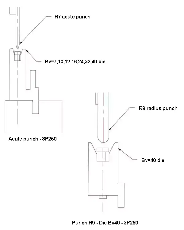
Fig.2 Three-point bending matrix
Table 2 The parameters of press brake, punch and die
| Die opening (Bv/mm) Brake press and punch type |
7 | 8 | 10 | 12 | 16 | 24 | 32 | 40 | |
|---|---|---|---|---|---|---|---|---|---|
| Opening V (Gooseneck punch) |
Beyeler | √ | |||||||
| FASTI-50 | √ | √ | √ | ||||||
| Three points (straight punch) |
3P250 | √ | √ | √ | √ | √ | √ | √ | |
Test method
The actual thickness of the samples was measured using a micrometer and the average of four pieces for each specific thickness was calculated. The specimens were bent using different bending dies at a bending angle of (90 ± 1)°, with the aim of ensuring that one side of the specimens was 50mm long, as illustrated in Figure 3.
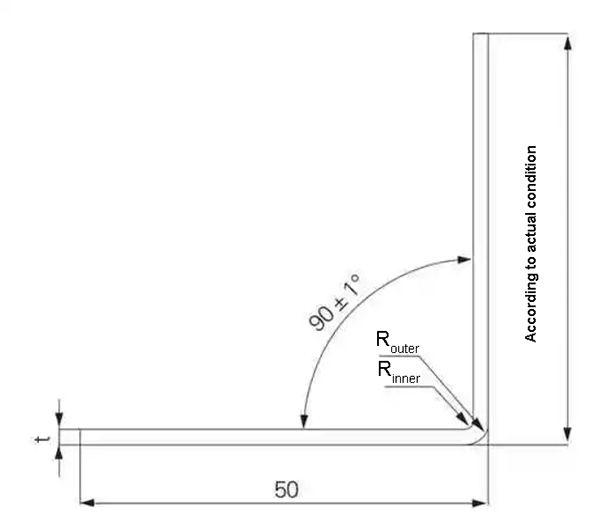
Figure 3 Flexure Test Diagram
Each thickness specification was repeated 5 times during the bending process. After the end of bending, the contours of the bending angle were scanned using an optical measuring instrument to calculate the external bending angle (R external) and the internal bending angle (R internal), as illustrated in Figure 4.
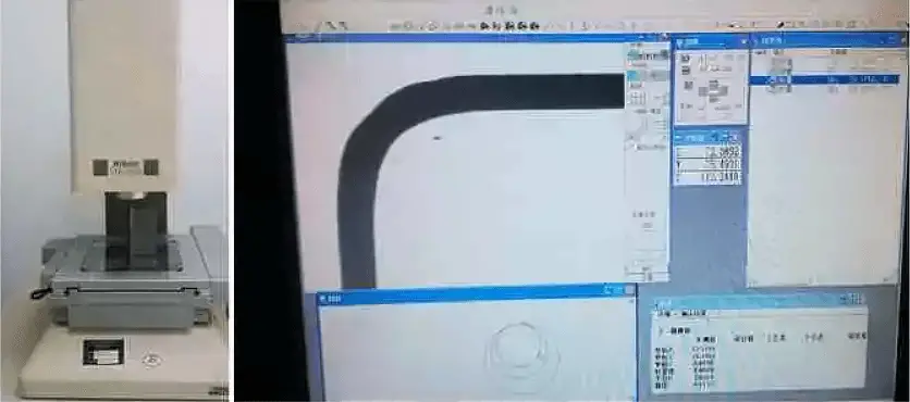
Fig. 4 Optical measuring instrument and measurement of bending angle R
A caliper was used to measure the length of both sides to calculate the bending coefficient. Each thickness specification was repeated 5 times and the average value was obtained.
Test results and analysis
The attached table is a compilation of the test results. The data displayed in the table includes the actual thickness of the test material, the inner and outer bend radius of 90°, the bend coefficient, and the bend thinning.
Actual material thickness
Table 3 compares the actual thickness of the sample, measured with a micrometer, to its nominal thickness.
Table 3 The actual thickness of the test materials (mm)
| Nominal thickness | 1.0 | 1.2 | 1.5 | 2.0 | 2.3 | 2.5 | 3.0 | 3.2 | 4.5 | 6.0 | |
|---|---|---|---|---|---|---|---|---|---|---|---|
| Actual thickness | SPCC | 1.00 | 1.18 | 1.48 | 2.01 | 2.50 | 2.97 | ||||
| SPHC | 3.13 | 4:20 am | 5.91 | ||||||||
| SUS304 (Remove film) |
0.93 | ||||||||||
| 804-GG | 2.26 | ||||||||||
The table reveals that the difference between the actual thickness of SPCC and its nominal thickness is within 0.03 mm. The actual thickness of the uncoated SUS304 material was found to be about 0.07 mm thinner than its nominal thickness. The actual thickness of the 4.5mm SPHC hot-rolled sheet was measured to be 4.2mm.
Doubling the internal angle R internal
By comparing the internal R under different bending conditions, it can be seen that the internal R is influenced by the material, plate thickness, bending method and bending tools.
Of these four factors, the situation of three other factors is the same:
- Internal R (SUS304) > Internal R (SPCC).
If the groove width in VB v = 12 mm, the internal R in SPCC with thickness of 1.2 mm and SUS304 is 1.85 mm and 2.09 mm, respectively.
- When the bending die is the same, for the same material, the internal R influence plate thickness is smaller.
For example, when B v = 12mm in three-point bending, internal R in the 1.0 ~ 2.0mm thickness of SUS304 is 2.33 ~ 2.51mm, the difference is not significant.
- R inner (three points) > R inner (V-groove).
Comparing the same groove width by bending the lower die (B v =7mm, 12mm and 16mm) shows that the internal R bending at three points is slightly greater than that at the V groove.
- The greater the width of slot B v, the greater the internal R and the greater the corresponding internal R
Figure 5 is a comparison of the three-point bending angles R for the bottom die slot width Bv is 24 mm, 32 mm and 40 mm, corresponding to about 4.0 mm, 4.7 mm and 5.9 mm of internal R respectively.
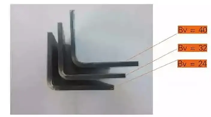
Fig. 5 Comparison of the inner radius of the 4.5 mm SPHC bend with different channel widths (three-point sharp punch)
Therefore, in addition to the width of the bending die groove B v the material, bending method (V groove and three points) also affects the internal bending R which we must pay attention to.
Reduction ratio and external bending angle R exterior
In the test, the difference between R outer and R inner is used to represent the average thickness near the bending angle, i.e. t' = R outer –R inner .
Thus, the reduction ratio is η = (t – t')/t.
From the data in the attached table, it can be seen that the thickness reduction occurred in all cases of this test case.
Most of the reduction rate is in the range of 6% to 15%, and the influence of material thickness, bending mode and groove width on the thinning rate is more complicated and the rule is difficult to identify.
However, it is clear that the thinning rate of SPHC is lower, around 4% to 6%.
OR of the internal test uses an optical measuring instrument to calculate the sweep, while the roundness value can be calculated.
(1) When Bv = 7 ~ 16mm, the roundness value of inner R and outer R is very small, mostly ≤ 0.05mm, indicating that the contours of the bent inner and outer corners perfectly match the roundness degree.
(2) When Bv = 24mm, 32mm and 40mm (all three-point type), the roundness values of inner R and outer R are slightly increased, exceeding 0.1 mm, which means that after the groove width Bv of the lower bending dies increase to 24 mm, the degree of arc of the inner and outer contours of the bend decreases.
Bending coefficient α
The schedule also provides the measured and calculated values of the bending coefficient test (currently used method to calculate the bending coefficient, calculation formula: α = 1.36t + 0.43R internal ).
For comparison, the difference is not large (in the calculation, the internal thickness t and R are both brought into the calculation by the actual test value), which indicates that the current bending coefficient formula α = 1.36t + 0 .43R internal is universal, the bending coefficient depends on two parameters on the actual thickness t of the material and the actual bending R internal .
Internal R is influenced by material, plate thickness, bending method and bending tool, internal real R is the simplest and most effective method.
For new materials or bent parts with other thicknesses, it is necessary to actually measure the actual thickness and the internal bending R of the bending tool.
Conclusion
Based on the above analysis, several conclusions can be obtained:
(1) Test results show the bending R inner R outer and bending coefficients of various commonly used thick sheets of SPCC, SPHC, SUS304, 804-GG in sheet metal workshop, CNC bending machines such as Beyeler, FASTI-50 and 3P250;
(2) Internal R is not only related to the bending die, but also to the material;
The test shows that the internal R of SUS304 is slightly larger than that of SPCC under the same bending parameters;
(3) When the other bending parameters are equal, the internal R of three-point bending is slightly larger than the bending of V-groove, so the bending work center should be considered when selecting the bending coefficient;
(4) The formula for calculating the internal flexural coefficient α=1.36t+0.43R is universal.
Accumulating the actual thickness of bending materials commonly used in the workshop and the corresponding bending mold forming internal R can calculate a more accurate bending coefficient.