In the spiral welded pipe production process, the next step involves cutting the end of the hot rolled coil after passing through the uncoiler and straightener. The head and tail of the steel plate are generally irregular in shape after hot rolling, as shown in Figure 1. It is necessary to align and weld the head and tail of the plate after they are cut.
Currently, the main cutting methods used are plate shearing and plasma cutting. Although plasma cutting has a slower cutting speed compared to plate shearing under the same plate width, most welded pipe units still prefer to use plate shearing.
There are two types of plate cutting: swing beam cutting and guillotine cutting. Guillotine shears have several advantages, including high cutting precision, high cutting force and high cutting speed, which make them widely used in the production of spiral welded pipes for large diameter pipes with thick walls.
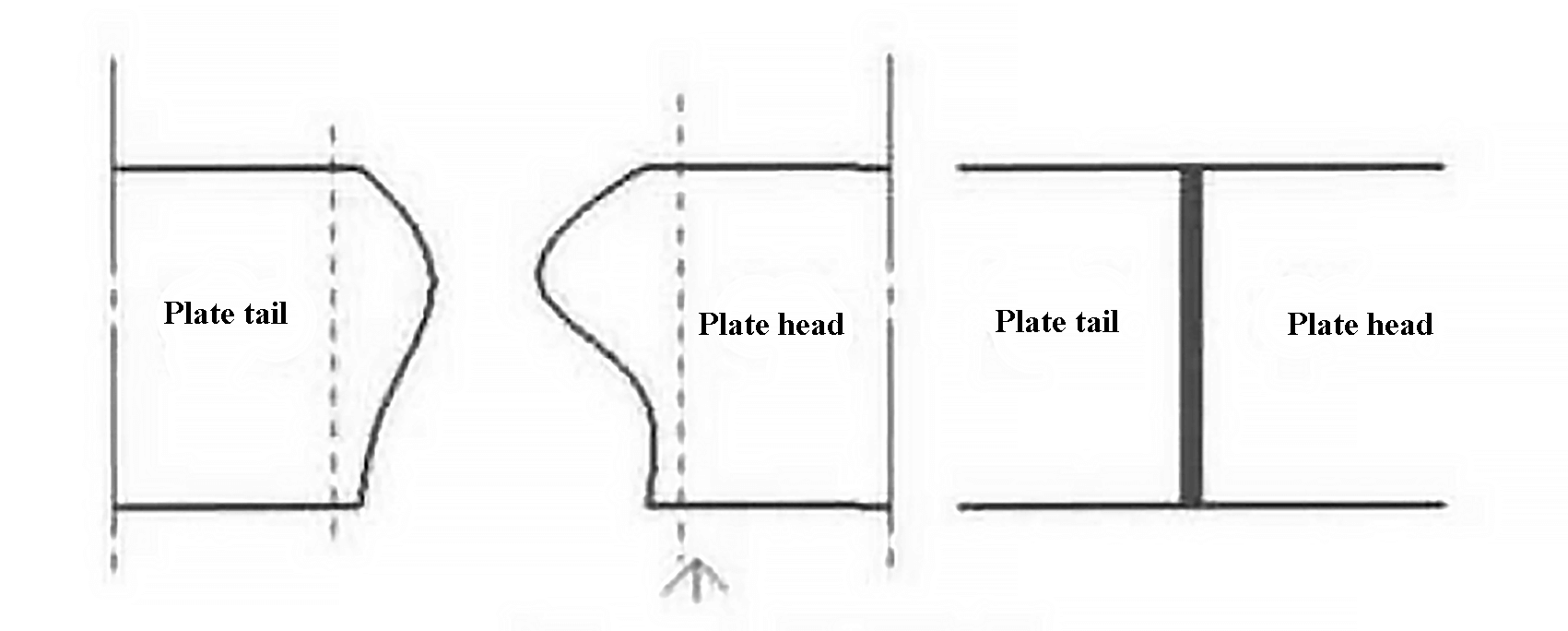
Fig.1 Schematic diagram of the head
1. Braking type schematic diagram plate shear system
Figure 3 shows the hydraulic schematic diagram of a guillotine. When the scissors are not in use, the pump is idle and the electromagnet is not energized. To adjust the shear angle, it is controlled by reversing valve 5. Figure 2 illustrates the shear process.
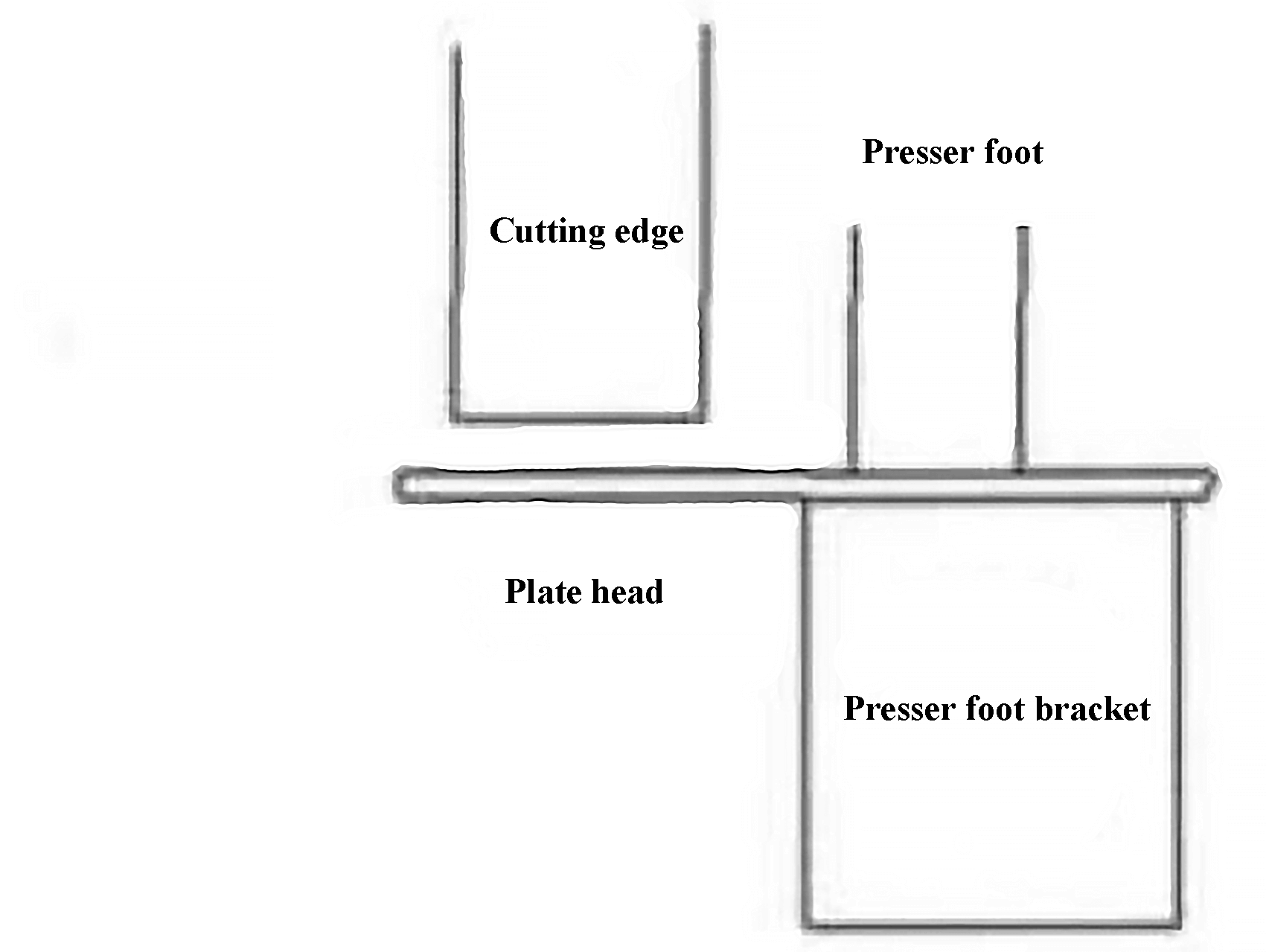
Fig. 2 Schematic diagram of the presser foot cut
Directional valve 7 is turned on to activate electromagnet Y4, which controls presser foot hydraulic cylinders 13 and 14 to clamp the head or tail of the plate. Directional valve 4 controls hydraulic cylinders 11 and 12 in series to perform shearing action, and directional valve 9 opens for oil return. The reversing valve 4 can also control the lifting of the cutting edge simultaneously. The specific electromagnet activation sequence is shown in Table 1.
Table 1 The electromagnet activation sequence
| Cut | TO 1 | A2 | A4 | Y7 turns on after 1 s delay |
|---|---|---|---|---|
| Elevator | TO 1 | A3 | ||
| Shear angle+ | TO 1 | A5 | ||
| Shear Angle- | TO 1 | A6 |
- 1 – Internal gear pump;
- 2 – Engine;
- 3 – Electromagnetic relief valve;
- 4 – Electromagnetic directional valve;
- 5 – Electromagnetic directional valve;
- 6 – Hydraulic control check valve;
- 7 – Electromagnetic directional valve;
- 8 – Relief valve;
- 9 – Electromagnetic ball valve;
- 10 – Hydraulic control check valve;
- 11 – Auxiliary shear cylinder;
- 12 -Main shear cylinder;
- 13 – Presser foot cylinder;
- 14 – Presser foot cylinder
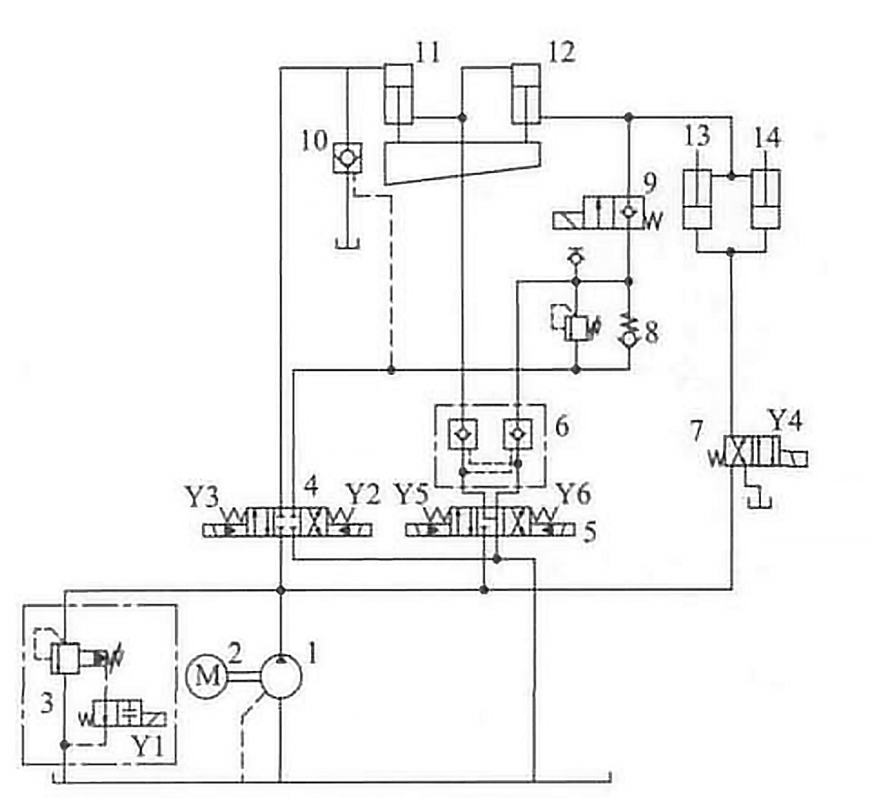
Fig. 3 Hydraulic schematic diagram of the guillotine
At present, the estimation of the shear force of plate shears generally uses Nosari's formula:
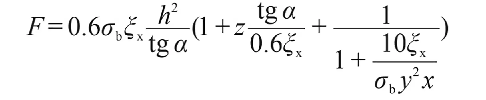
In the formula:
- f – cutting force;
- σ b – material resistance limit;
- ξ x – elongation of the cut sheet;
- h – sheet thickness;
- α – blade angle;
- z – bending force coefficient of the sheared piece;
- y – relative value of the lateral clearance of the front edge;
- x – press influence coefficient.
According to the data, the values of ξx, z, y and x are 0.25, 0.95, 0.083 and 7.7, respectively. Figure 4 shows the quantitative analysis of σb, h and α, which reveals that the ultimate strength and plate thickness are directly proportional to the cutting force F, while the blade inclination angle is inversely proportional to the cutting force.
Based on this conclusion, common faults in the main hydraulic system of this type of guillotine were analyzed and summarized.
2. Problem analysis
2.1 No pressure in the system
To troubleshoot the problem, it is important to first determine if the motor is reversing and check the coupling between the motor and pump for any damage. If there is still no pressure after deleting these two points, relief valve 3 failure may be suspected. The cause of the problem may be due to a blocked damping hole in the relief valve, or a stuck directional valve or leak. serious damage to the relief valve.
2.2 S system pressure does not rise
Most failures are valve related. Internal leaks and a stuck valve core can prevent system pressure from rising, and these problems can be solved by controlling the corresponding solenoid valve one by one.
However, before troubleshooting the valve, it is important to check the system tank first. If there are a lot of bubbles in the oil tank, it indicates that the pump is not working properly. In this case, first check the oil level in the tank. If the hydraulic oil level is sufficient, inspect the plum blossom pad or nylon pin on the coupling for damage. If these problems are ruled out, it can be concluded that the pump has been damaged. If there are iron and copper chips in the oil, this indicates that the pump and valve are badly worn and causing insufficient pressure.
This type of scissors does not have a cooling system. If the operator does not turn off electromagnets Y1 and Y3 after work is completed and the engine is not turned off, a significant amount of heat will be generated in a short space of time, causing the oil temperature to rise and degrade.
After troubleshooting the pump and valve, the sealing problem in the hydraulic cylinder can be directly identified, leading to system pressure failure.
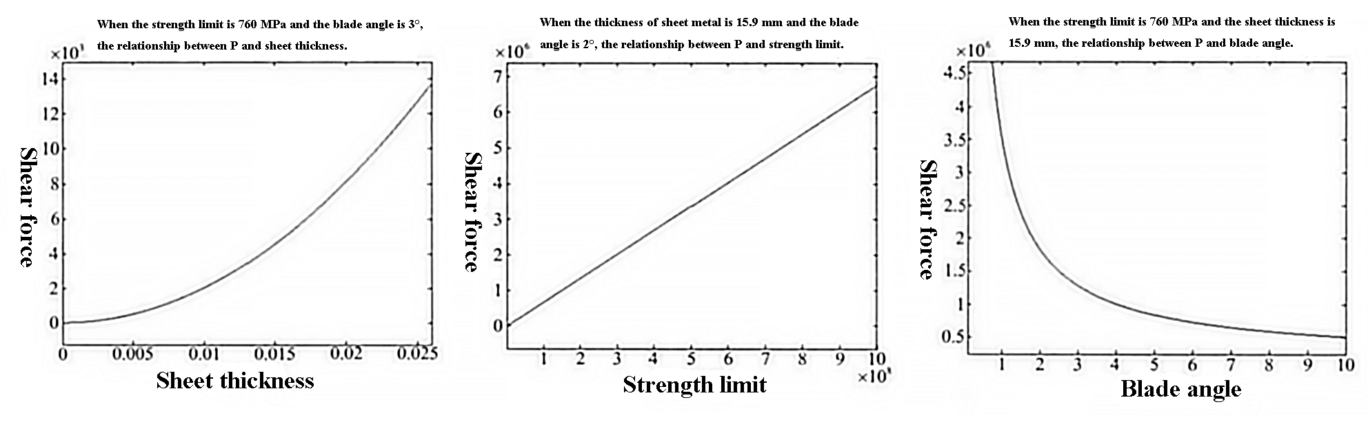
Fig. 4 The relationship between the parameter and F
2.3 Automatic drop of the presser foot and scissors
Figure 5 shows the structure of the presser foot on a plate scissor. Due to its weight, the presser foot's hydraulic cylinder has a tendency to fall. The schematic diagram helps identify the reason for the presser foot hydraulic cylinder falling out.
As shown in the diagram, the rod cavities of the hydraulic cylinders 13 and 14 are connected to the rod cavities of the hydraulic cylinder 12 and the solenoid valve 9. If the hydraulic cylinder 12 is working properly, the solenoid valve 9 should be the first point of consideration. If the solenoid valve 9 is removed, the oil in the rod cavities of the hydraulic cylinders 13 and 14 will be connected to the B port of the directional solenoid valve 4 and the control oil port of the hydraulic control check valve 10, which will result in leak over time.
To prevent leakage, the reversing valve 9 uses a seat valve structure. If the electromagnet Y7 is activated incorrectly or the sealing surface of the seat valve loses its sealing effect, the presser foot will fall down again.
Another common cause of the presser foot falling out is damage to the seals on hydraulic cylinders 11 and 12.
Fig. 5 Cutting machine presser foot mechanism
Regarding the automatic fall of the cutting edge, as shown in Figure 3, the scissors are controlled by two hydraulic cylinders connected in series. Electromagnetic directional valves 4 and 5 control the different scissor actions. The rod diameter, cylinder diameter and stroke of hydraulic cylinder 11 are 212 mm, 320 mm and 185 mm respectively. The rod diameter, cylinder diameter and stroke of hydraulic cylinder 12 are 212 mm, 240 mm and 185 mm respectively. If the seals and gaskets of the two hydraulic cylinders leak, the cutting blade will fall automatically. Like the presser foot, the electromagnetic ball valve 9 will also fall automatically.
Another possible cause of automatic dropout is solenoid valve 5 and hydraulic lock 6. If the hydraulic lock 6 O-ring is not installed correctly or the oil temperature becomes too high, the O-ring may become stuck in the hydraulic. lock and block the oil circuit, preventing the hydraulic lock from closing properly. This will cause the oil from the two hydraulic cylinders to return to the oil tank through the electromagnetic directional valve 5 (“J-type function”), resulting in the cutter falling. The problem can be solved by replacing the “O” ring.
2.4 The cutting edge cannot move the plate
It has been determined that the ultimate strength of the steel plate, the thickness of the steel plate and the shear angle play a role in the shearing process. For example, a 15.9 mm thick X70 steel plate requires a pressure of approximately 12.5 MPa. However, in practice, it is common for the steel plate not to cut even when the pressure is set to 15 MPa or 20 MPa and there is no failure of oil leakage in the equipment. In these cases it is necessary to identify the problem by examining the structure of the equipment.
Figure 4 shows that the difference in shear force between a blade angle of 2.5° and 10° is almost 5 times, so the failure of the shear process is mainly due to the blade angle. During equipment operation, incorrect adjustment of the hydraulic shear cylinder limit may result in the required angle for the shearing process not being achieved, which can be resolved by adjusting the hydraulic shear cylinder limit.
As shown in Figure 6, when cutting, the cutting edge generally cuts first, but the presser foot cylinder does not press down, causing the steel plate to curl and not cut. Electromagnet Y2, which controls cutting, and electromagnet Y4, which controls the presser foot, are turned on at the same time, so the problem is not related to the startup sequence.
The speed of the shear hydraulic cylinder 11 is v 1 =q/s 11 and the speed of the presser hydraulic cylinder is v 2 =q/2/s 13 .
Among them, S. 11 is the piston area of hydraulic cylinder 11, with 0.08 m 2 .
S 13 is the piston area of hydraulic cylinder 13, with 0.0095 m 2 then v 2 ≈4v 1 .
Therefore, in this system, the cutting and presser timing can be adjusted by adjusting the direct acting relief valve 8.
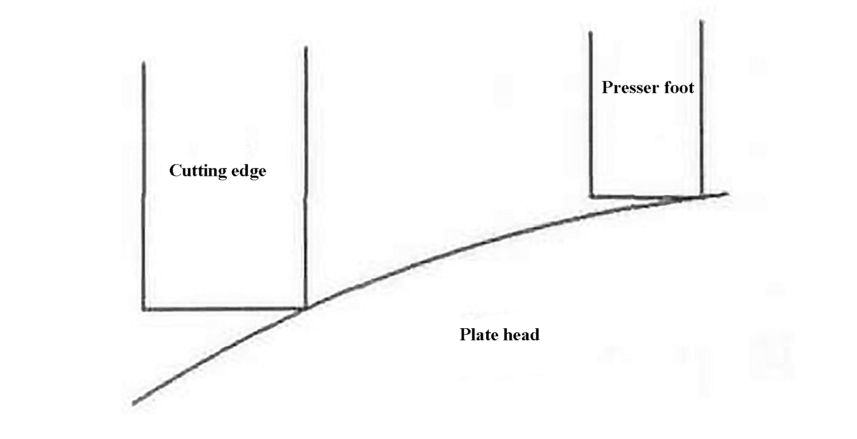
Fig. 6 Schematic diagram of shear rupture
Relief valve 8 serves two main purposes in the system. First, it increases oil return pressure to prevent the cutting cylinder from dragging. Secondly, it can be used to adjust the speed of the cutter and presser foot.
The characteristic flow equation is known as:
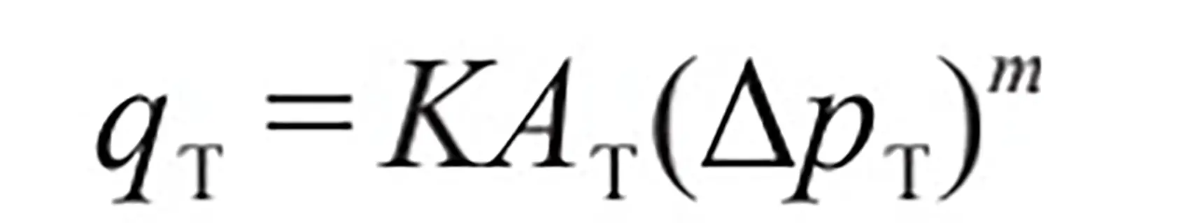
It can be determined that the flow g through relief valve 8 is proportional to the pressure difference △p between P and T.
When shearing, the pressure p 12 in the joint of the rod cavity of the hydraulic cylinder 12 is greater than the sum of the pressure p 1314 of the rod cavity of two hydraulic cylinders of the presser foot 13 and 14.
Therefore, when the return oil flow g cannot be greater than or equal to p 12 +p 1314 page. 12 will exert a reaction force on hydraulic cylinders 13 and 14 to decrease the pressure velocity of hydraulic cylinders 13 and 14, resulting in the failure shown in Figure 6.
Currently, the relief valve 8 pressure can be adjusted to change the return oil flow (qT), resulting in the tamper effect depicted in Figure 2.
As illustrated in Figure 7, the hydraulic shear cylinder is attached to the rack through the cylinder steps.
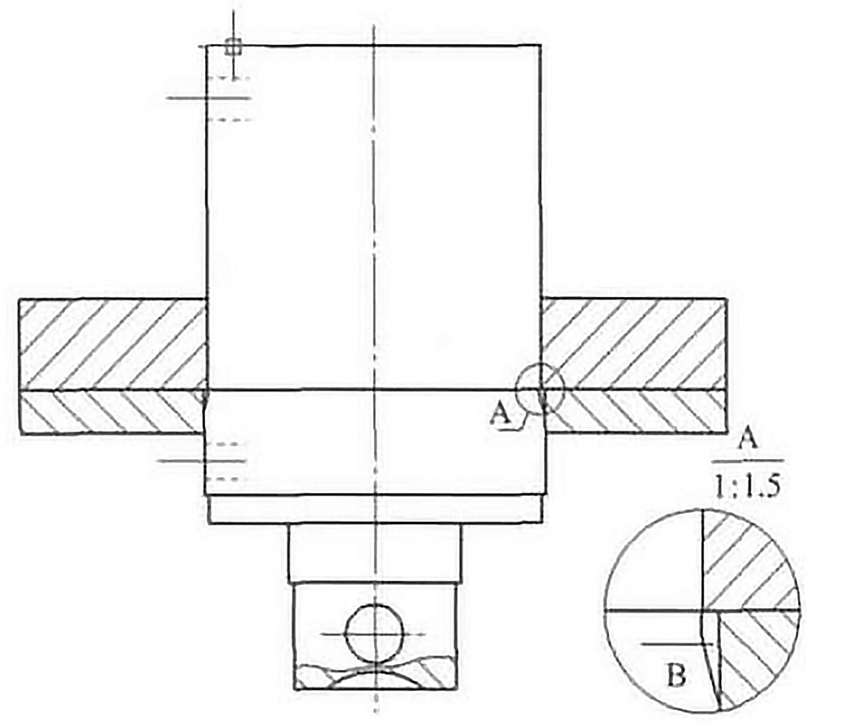
When the step at point A becomes worn, similar to point B, the steel plate applies an upward force to the cutting edge, causing the hydraulic cylinder to move upward due to the force reaction.
Instantly, the inclination angle of the blade increases and the shear force decreases, which is a significant cause of the shear failure of the steel plate.
3. Conclusion
This article examines some failures in the hydraulic system of a guillotine.
Based on recent years of operating experience, equipment failures are often complex.
Mechanical failures often coincide with hydraulic failures, and hydraulic failures coincide with electrical failures.
However, by using reference drawings, performing on-site analysis, and establishing a database of equipment failures, it is possible to quickly determine the source of equipment failure and ensure normal operation.