The hydraulic control technology of hydraulic press brakes has gone through three distinct control stages: proportional pressure control, servo proportional flow control and electro-hydraulic hybrid control technology.
This development represents a progression from basic control to precise control, ultimately resulting in the ability to save energy and simultaneously reduce operating costs.
With the implementation of electro-hydraulic hybrid technology in hydraulic bending machines, there has been a significant shift from coarse to refined technology.
Review of the development of electro-hydraulic mixing technology
When electro-hydraulic hybrid technology was first introduced, it was heavily influenced by superior CNC systems and technical knowledge. However, it simply replaced the asynchronous motor with a servo motor and used a multi-stage speed control method that estimated the hydraulic flow demand for each executive step of the bending cycle.
Due to this estimate, the oil pump driven by the servomotor must produce more flow than necessary. Excess flow is then forced to overflow through the relief valve, resulting in loss of power. Furthermore, this control method is unstable and cannot adapt to the requirements of various processing techniques. Plunger speed control is inflexible and manufacturing costs are high.
Fortunately, with the advancement of electro-hydraulic pump control technology and the accumulation of experience in various industries, the hydraulic press brake has been further optimized with a torque limiting control scheme, as illustrated in Figure 1.
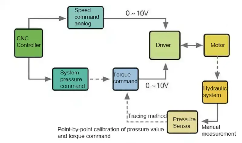
Figure 1 Structural diagram of the torque limiting control scheme
This control scheme can not only solve the basic overflow situation, but also further reduce the pressure proportional valve, which can save some hydraulic system costs.
Currently, this program is mainly used to support the analog hydraulic flow control of the NC system. However, there are still some CNC systems on the market that do not support dual analog work (hydraulic flow and hydraulic pressure) and can only use a combination of switching to form multi-stage speed flow control with analog pressure command.
In addition to this apparent deficiency, the torque limiting control scheme has another important limitation.
Before we delve into this, let's briefly describe the working principle of torque limiting control on a hydraulic press brake, as shown in Figure 2.
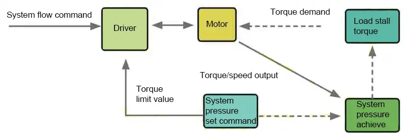
Figure 2 Correspondence between pressure and torque
Engine output torque is controlled by system pressure mapping, which is achieved through a basic PID control system. Although the principle is simple and easy to understand, there is a non-linear relationship between the pressure command, the torque limit value and the actual pressure value during the specific implementation.
To fix this problem, the CNC system requires point plotting. The pressure accuracy requirement determines the number of tracking points required and the corresponding adjustment man hours will also increase accordingly. If the tracking points are reduced, the pressure deviation will increase.
In light of the above-mentioned practical application defects, we propose corresponding solutions.
Full closed loop pressure control mode
Add a pressure sensor to the control system to provide real-time feedback of system pressure.
The advantage of this is that it completely eliminates overflow, allowing the system to more accurately meet the process flow demand in real time.
The pressure sensor outputs only the required amount and can maintain pressure accuracy within 0.1 MPa, significantly reducing adjustment time, as shown in Figure 3.
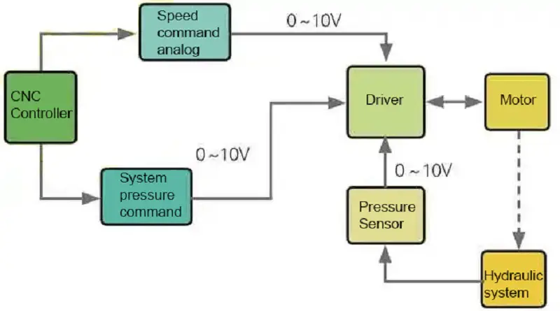
Figure 3 Structural diagram of the complete closed-loop pressure control mode
Multistage flow pressure closed loop mode
In response to the prevalence of CNC systems for bending machines that support only flow switching commands on the market, our team has optimized the hybrid servo drive control firmware. This optimization allows the press brake to adopt a numerical control system that allows more precise pressure control without overflow.
As a result, our solution aims to improve accuracy, reduce energy consumption and reduce costs for our customers.
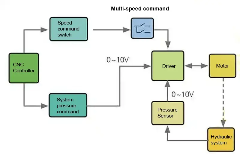
Figure 4 Structural diagram of multistage flow control
The real case
The specific configuration and technical requirements of the plan are presented in Table 1.
Table 1 Configuration and technical requirements
| NO. | Name | Number | Technical requirements |
| 1 | CNC system | 1 | |
| two | Oil-electric servo motor | 1 | Maximum system pressure 30MPa |
| 3 | Oil-electric servo driver | 1 | Maximum engine speed 2,000 rpm |
| 4 | Rear shock absorber servo driver | 1 | Ram fast deceleration speed 150 mm/s |
| 5 | Rear shock absorber servo motor | 1 | Ram decelerates speed 10mm/s |
| 6 | Pressure Sensor | 1 | Ram accelerate speed 120mm/s |
| 7 | Internal Gear Oil Pump | 1 |
As shown in Figure 5, during the actual bending process, the pressure output and demand setting closely align in the pressure holding state. Furthermore, the output flow will be automatically adjusted according to the actual process.
Between them:
- A quick section down;
- Section B power supply;
- C section pressure retention;
- Section D pressure relief;
- Section E accelerated.
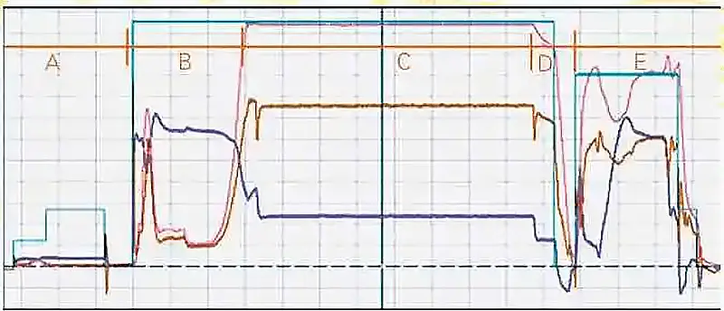
Figure 5 Full Closed Loop Pressure Control Mode
- light blue line: pressure command;
- pink line: real pressure;
- blue line: outflow;
- brown line: output torque.
As shown in Figure 6, the same control effect successfully solves the overflow problem in various processes within the simple multi-stage speed control scheme. This solution guarantees accurate pressure control and provides significant economic benefits.
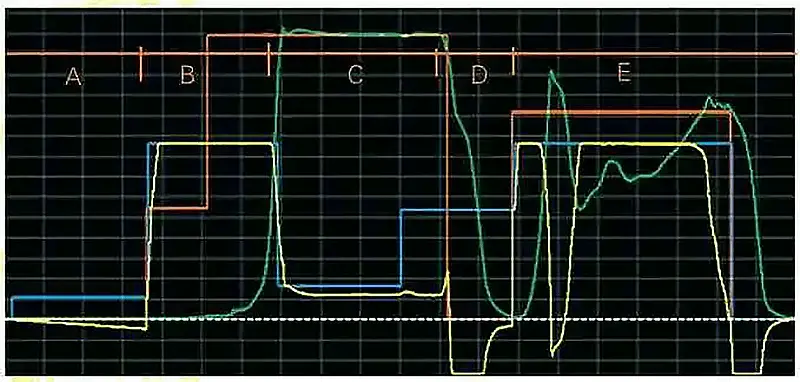
Figure 6 Multi-stage flow pressure control mode
Between them:
- A quick section down;
- Section B power supply;
- C section pressure retention;
- Section D pressure relief;
- Section E accelerated.
- red line: pressure command;
- green line: real pressure;
- blue line: flow command;
- yellow line: real flow.
Conclusion
Compared with the commonly used electro-hydraulic control technology, our company's hydraulic press brake pump control technique offers a superior control mechanism. It can meet the requirements of no overflow, oil temperature reduction, noise reduction and accuracy improvement simultaneously without significantly increasing costs.
Furthermore, this technique can reduce costs and increase benefits for press brake manufacturers and end users, making it an ideal solution to replace the electro-hydraulic control technology of the hydraulic press brake.