
The surface is an important aspect of machined parts. Surface finish has a significant impact on the durability and performance of a product. Therefore, it is important to understand surface roughness and its role.
What is surface finish/surface roughness?
The condition of a surface is called surface texture or surface topography. It refers to the slight local deviations of a surface from a perfectly flat surface (a real plane).
The term “surface finish” generally refers to the degree of polish or surface texture of a part or component. One of the parameters of surface texture is surface roughness. These parameters quantify surface finish properties to regulate the manufacturing process or predict the behavior of a component during use.
Surface quality parameters
Surface quality parameters are also called surface texture parameters. They are divided into three characteristics: roughness, waviness and location. Roughness usually consists of smaller irregularities, while waviness consists of larger irregularities. Location refers to the direction of the predominant grain or texture on the surface.
Importance of surface roughness in technical production

Here are some important reasons why surface roughness is important in various manufacturing processes.
• Irregularities in the surface can serve as a breeding ground for cracks or corrosion. Therefore, roughness is a strong indicator of the future performance of a mechanical component. Some applications may also be necessary to improve the adhesion of cosmetic finishes such as painting, powder coating or galvanizing.
• Engineers must maintain surface control to develop consistent and reliable production processes for each product. In many surface finishes, surface measurement can be a critical element in maintaining control of the manufacturing process, monitoring it to ensure it is within certain parameters when an accurate surface finish is required. Failure of a constructed item often begins at the surface, whether due to a single manufacturing defect or a gradual deterioration in surface quality.
• Surface treatment can optimize and improve the electrical conductivity of the surface. Increases product wear resistance, reduces friction and is crucial for corrosion and chemical resistance. It also gives products a special visual appearance. It also contributes to the adhesion of paints and coatings. For this reason, treatment processes have become the preferred approach to achieving the desired surface treatment on various machined and manufactured objects.
5 factors that influence surface texture
When the surfaces of two objects come into contact, the quality of the surface finish has a significant impact on performance and durability. Below are some of the factors that affect surface finish:
temperature
Volume is influenced by temperature. As the temperature increases, metals expand while polymers can deform. As a result, the surface finish of a component can be influenced by the temperature of the material being cut. Temperatures above the ideal temperature for the cutting process of the material in question often result in irregular surfaces and increased surface roughness, especially when using mechanical methods.
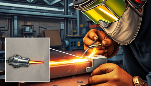
Cutting techniques
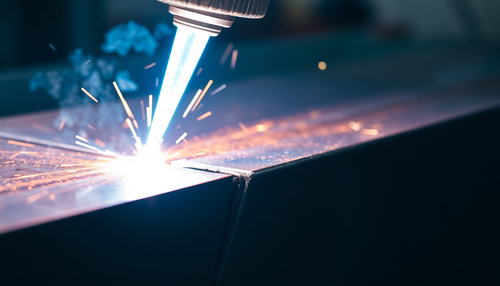
Metal blades are traditionally used in cutting instruments and machines. Lasers and high-pressure water, on the other hand, have become popular alternatives to traditional mechanical cutting methods. Overall, new technologies lead to more noticeable results, including smooth surfaces. Laser cutting offers numerous advantages over conventional cutting technologies, such as greater cutting precision and fewer rough surfaces. A waterjet cutter offers advantages such as more powerful surface processing on small parts.
Material removal rate and advance
Material removal rate (MRR) is the amount of material removed per unit of time. Shows how long it takes to remove a certain amount of material from a workpiece. Feed is defined as the distance the tool travels along or within the workpiece for each tool point passed per unit time. Both aspects influence the quality of a surface treatment.
cutting instruments
The surface finish of a part is determined by the type and quality of the machines used for cutting. Cutting speed, feed and depth can be changed on cutting machines. These variables are changed depending on the type of material to be cut and the size of the component to be manufactured to avoid a very rough surface.
Cutting depth and cutting speed
Perpendicular to the machined surface, depth of cut is the penetration of the tool's cutting edge into the workpiece material with each pass. Cutting speed is the speed at which the cutting edge of a tool moves over the surface of a part in a given time. The tool may become dull due to excessive heat generation if the cutting speed is too high. When cutting speed increases, machining time increases, resulting in reduced productivity.
How do you measure surface roughness?

Surface roughness is a way of quantifying the number of irregularities on a surface. The parameter Ra represents the arithmetic mean of all surface elevations measured in a given area. As mentioned above, they are divided into three characteristics: roughness, waviness and shape. These factors can influence surface properties.
Therefore, there are several ways to measure surface roughness. The most important measurement techniques are direct measurement, comparative measurement, non-contact measurement and in-process measurement.
• Direct Methods Assess surface finish by dragging a pencil perpendicular to the surface and dragging it along the surface. Another method for evaluating surface roughness in magnetic materials is inductance. In this method, an inductance transducer uses electromagnetic radiation to measure the distance to the test surface. This test produces a parametric value that can be used to compare roughness levels.
• Comparison techniques . Comparative techniques use surface roughness samples prepared using the same equipment, process and material as the surface being evaluated. The visual and tactile senses compare a sample with known surface roughness. Due to the subjective nature of the process, this technique is best suited for non-critical applications.
• Instead of using a pen in contact methods, non-contact methods use sound or light. Optical instruments are divided into several categories, including confocal and white light interference. They differ in the principle underlying them. Electron microscopy techniques are also used, but the devices used are limited by their small fields of view.
• In-process methods allow for continuous surface monitoring during machining or other processes, which can provide valuable feedback to the operator. Additionally, in-process methods can provide more accurate results than other methods because they measure the surface under conditions closer to the actual application.
Additionally, sound is used to determine surface properties. Ultrasonic scattering involves sending an ultrasonic pulse to the surface. Ultrasonic waves are converted and reflected from the testing device. The surface roughness properties are then calculated based on the reflected waves.
Surface roughness can also be measured with light by illuminating the surface with a laser beam and measuring the intensity of the reflected light. The rougher the surface, the more the light is scattered and the lower the intensity of the reflected light.
Types of Surface Finish Testing Equipment
Many methods use different equipment to test surface texture or rough surfaces. Some of the devices are listed below:
Profile technique
The surface is measured with a high-resolution measuring probe. The sensitivity of this process is more comparable to that of a gramophone needle. It is possible that a CNC probe may not be effective.
Microscopy technology
These qualitative approaches focus on comparing and contrasting two different things. The results provide useful information about the peaks and valleys found on various surfaces.
technology area
These methods measure a limited surface area. They provide a statistical average of surface peaks and depths. Examples include ultrasonic scattering, capacitance probes, optical scattering, and others. Area-based approaches are easier to automate and implement.
Understanding Surface Roughness Symbols: From RA to RZ

Correct roughness measurement is crucial in technical applications, as surfaces must be within the desired roughness limits for quality reasons. Statistical descriptors, intensity values, and texture descriptors can be used to evaluate surface condition.
Ra (average surface roughness)
The most commonly used metric to evaluate surface finish is Ra, or deviation from the arithmetic mean, which measures the average surface roughness of a part. Ra quantifies the deviation of a roughness curve from the centerline. Additionally, the surface texture diagram Ra is often used for absolute values when describing, measuring, and reproducing surface topology. However, it has significant flaws that make additional factors useful.
Rmax (vertical distance from peak to deepest valley)
Burrs and scratches are prime candidates for this roughness property. However, this may not be clear when using the Ra surface quality table. Rmax, on the other hand, is extremely sensitive to these irregularities.
Rz (maximum average profile height)
Rz typically measures the maximum average height of a surface trajectory. The average results of the five largest differences between the highest peaks and lowest valleys across the area determine this parameter. The Ra parameter may ignore some extremes, resulting in imprecise or imprecise measurements; Rz can help eliminate some of these errors.
Centerline Average (CLA)
Centerline mean is defined as the arithmetic mean height of peaks and valleys determined by a profilometer or optical interferometer when measuring surface roughness. It is considered the most suitable method for measuring surface roughness.
Ra compared to RMS
As you know, various abbreviations are used in surface finishing, including Ra, Rsk, Rq, Rku, Rz, RMS, etc. Micrometers or even microinches are the most common units of surface finish. Additionally, the lower number indicates a finer surface quality. The following surface roughness chart compares the two scales Ra and RMS for manufacturing processes.
| Approximate surface roughness conversion table | ||||
| Roughness Level Numbers | American system | Metric system | ||
| Ra (µin) | RMS value (µin) | Ra(µm) | RMS value (µm) | |
| N12 | 2000 | 2200 | 50 | 55 |
| N11 | 1000 | 1100 | 25 | 27.5 |
| N10 | 500 | 550 | 12.5 | 13.75 |
| N9 | 250 | 275 | 8.3 | 9.13 |
| N8 | 125 | 137.5 | 3.2 | 3.52 |
| N7 | 63 | 69.3 | 1.6 | 1.76 |
| N6 | 32 | 35.2 | 0.8 | 0.88 |
| N5 | 16 | 17.6 | 0.4 | 0.44 |
| N4 | 8th | 8.8 | 0.2 | 0.22 |
| N3 | 4 | 4.4 | 0.1 | 0.11 |
| N2 | two | 2.2 | 0.05 | 0.055 |
| number 1 | 1 | 1.1 | 0.025 | 0.035 |
How to choose suitable surface roughness for CNC machining?

CNC machining is a precise and accurate manufacturing process that can produce parts with tolerances down to 0.025 mm. However, machining processes can leave cut marks on the surface of the final product. The surface roughness of a part after machining is rarely random.
Instead, measures are taken to ensure that a certain roughness is achieved. This means that the surface roughness values are predetermined. Certain Ra values are considered industry standards in manufacturing as set out in ISO 4287.
In CNC machining, these are the values that can be specified. They are used in various manufacturing and post-processing processes and range in size from 25 µm to 0.025 µm. The lower the Ra value, the more machining efforts/operations are required, hence the quality control.
Below are some of the Ra values:
3.2μmRa
This is the typical surface treatment for commercial machines. It is acceptable for most consumer parts and smooth surfaces, but there will be visible cut marks.
1.6μmRa
With this option, crop marks are usually only marginally visible. This Ra value is suitable for slow-moving surfaces and light loads and is recommended for tight fits and stressed parts.
0.8μmRa
This high-quality surface treatment requires careful and detailed work, which adds effort. It is essential for parts subject to high stress.
0.4μmRa
Surface roughness of this thickness requires more work and should only be ordered if smoothness is the highest priority. They are ideal for areas subject to high tension or stress.
University Degree
Surface finishing is the process by which a manufactured part receives the desired surface roughness. It is the result of the manufacturing processes used and can have a major impact on the function, aesthetics and durability of the final product.
Common questions
What are the units of Ra?
The units of Ra are micrometers and microinches.
What is a 125 surface finish?
A 125 finish is 0.000125 millionths of an inch.
What is the relationship between Ra and surface smoothness?
The lower the Ra value, the greater the smoothness of the surface and vice versa.
What does RMS 63 mean?
RMS 63 indicates that the surface is smoother and has a better finish.