1. Preparation
Before installation, the quality of each component must be examined (including model, values, voltage resistance and polarity). Any components that do not meet these standards must be replaced immediately.
Next, the cables of each component should be cleaned with sandpaper or a knife to expose the metallic shine and then coated with flux for buffing.
Finally, the component cables must be bent to the lengths required for their placement on the circuit board.
When bending cables, make sure the markings are facing outwards. Hold the base of the component with tweezers in one hand and bend the wire with the other, creating an arc at the bend.
2. Installation
Installation must be guided by the installation diagram. Typically, the diagram is oriented with the copper foil side of the printed circuit board facing up and the component side facing down.
Start by installing large components, then insert smaller components, such as resistors and capacitors, into the solder holes.
Components should be arranged neatly and aesthetically, with model numbers and values facing outward for easy visibility, which will facilitate inspection and maintenance. Finally, after testing the transistors or integrated circuits, they can be inserted into the solder holes and soldered.
Welding Techniques:
After installing the components on the printed circuit board, the next step is soldering.
You can solder each component individually as they are installed, or install all the components first and then solder them all at once.
In any case, the same general requirements apply.
3 . Cleaning the soldering iron tip
The tip of the soldering iron must be kept clean and free from soldering slag and other oxidants.
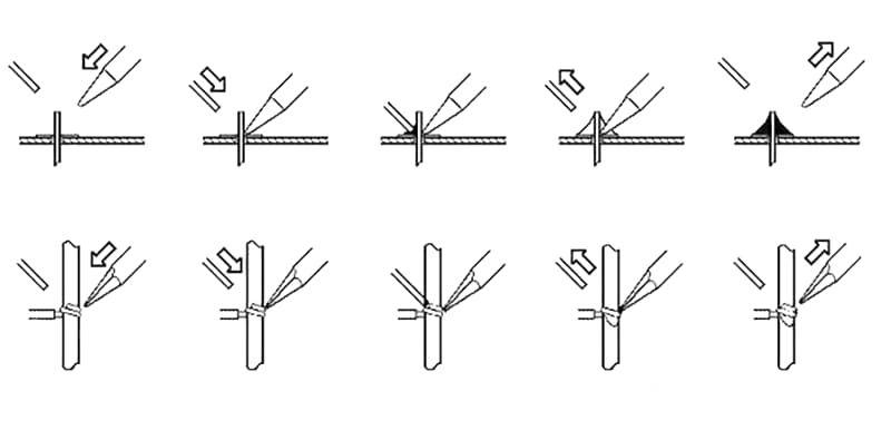
4 . Heating the soldering area
Apply adequate pressure to the area being heated with the soldering iron. The angle between the iron and the copper sheet should be about 40 to 60 degrees.
When soldering components to a printed circuit board, make sure the iron is in contact with both items to be soldered so that the heat is distributed evenly.
For components with low thermal capacity, such as thin wires on a printed circuit board, this step can be skipped.
During heating, all parts of the component that require tinning must be heated evenly, not just one part. Avoid adding pressure with the iron to avoid damage or hidden dangers.
5. Welding supply
First, apply a small amount of solder to the copper foil and component supply points to improve thermal conductivity.
If there are pins, add a small amount of solder to the cut surface of the pins to prevent oxidation.
Due to the nature of solder flowing from low to high temperatures, slowly feed the solder wire from a point away from the soldering iron, adjusting the amount and speed of supply accordingly.
Avoid supplying solder directly to the tip of the soldering iron. The tip of the soldering iron must be placed in a position where it can simultaneously heat the copper foil and the component.
Depending on the size and material of the copper foil, if the copper foil and the component are large, the contact area of the soldering iron tip should be large; conversely, if they are small, the contact area must be small.
This allows the copper foil and component to reach the same temperature at the same time.
6. Removing Solder
Once a certain amount of solder wire has melted, immediately move the solder wire 45° to the upper left corner.
7. Removing the soldering iron
The soldering iron must be removed to the upper right corner. Do not move the soldering iron until the solder is completely spread over the edge of the copper foil.
The time between step 5 and step 7 should be approximately 1 to 2 seconds. For welding quality, the contact time between the soldering iron and the copper foil should not exceed 3 seconds.
Removing the soldering iron requires precision. The time, angle and direction of removal of the iron are essential for the formation of the solder joint. The direction of removal of the soldering iron can affect the amount of tin in the solder joint.
8. Placing the soldering iron
Place the tip of the soldering iron – still glued with solder – onto the soldering iron holder.

Welding Precautions:
1) When carrying out tin welding, follow the sequence from left to right and top to bottom to avoid inspection or repair failures during welding.
2) Clean the soldering iron tip frequently during soldering to avoid defects such as false soldering, pinholes and excessive soldering caused by debris on the soldering iron tip.
3) Do not add solder to the soldering iron tip on the substrate. During the production process, do not shake, beat or shake the solder to prevent slag or solder granules from falling onto the substrate.
4) When pressing or disassembling components, first add solder to the copper foil surface of the circuit board. Ensure uniform heating to prevent the rosin from becoming ineffective or the copper foil from curling and damaging the circuit.
5) After using the soldering iron, place it firmly on the soldering iron holder. Be careful not to touch the soldering iron tip with wires or other debris to avoid burning the wires, causing electrical leaks or other accidents.
6) Keep the soldering iron tip clean: During soldering, the soldering iron tip remains at a high temperature and is in contact with slightly acidic substances, such as flux, making its surface prone to oxidation, corrosion and accumulation of impurities black.
These impurities form an insulating layer, making heat transfer between the soldering iron tip and the soldered components difficult.
Therefore, always clean the soldering iron tip with a damp cloth or wet wood fiber sponge. For regular soldering iron tips, a file can be used to remove the surface oxidation layer when corrosion and contamination are severe. However, this method should never be used for long-lasting soldering iron tips.
7) Use an adequate amount of flux: An adequate amount of flux is very beneficial for soldering. Excessive use of rosin flux requires removal of excess flux after soldering and prolongs heating time, reducing work efficiency.
If the heating time is insufficient, it is easy to form a “slag inclusion” defect. When soldering switches and connectors, excess flux may flow to the contact point, causing poor contact.
The appropriate amount of flux must be sufficient to wet the part that will form the solder joint and must not flow through the holes in the printed circuit board. For welding using resin core welding wire, there is basically no need to apply additional flux.
8) To reduce the harm of chemicals volatilized during flux heating to humans and to reduce the inhalation of harmful gases, the distance from the soldering iron to the nose should generally not be less than 20 cm, generally about 30 cm it's adequate.