Our common sheet metal processing consists of six main steps, described in detail below:
- Design drawing
- Laser Processing/NC Stamping
- Doubling
- Welding training
- Electrostatic powder coating/liquid painting
- Packaging and Delivery
Steps to complete the production of sheet metal products
1. Drawing drawing
Customers typically provide drawings or samples, which are analyzed and designed by the company's engineering team. This process results in the creation of detailed processing drawings and assembly drawings. These are then sent to the production department for processing.
2. Laser processing
The laser cutting machine is capable of cutting carbon steel, stainless steel and various other materials. The result is a smooth, clean, precise cut with a beautiful edge. This method is especially advantageous for parts with curved shapes and is an indispensable processing technique compared to traditional CNC stamping.
3. CNC stamping
CNC turret punch is mainly used for products with thin material thickness, generally less than 2.5mm. This method is suitable for sheet metal parts that require multiple holes or the need to use a specialized mold for processing. When the number of parts is large, CNC stamping has a cost advantage over other methods.
4. Push-up
If the majority of parts need to be bent after cutting, press brakes will be needed to complete the bending process. The CNC press brake is preferred because it is not only faster but also more accurate.
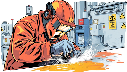
5. Welding Training
Generally, after the stamping process, the part needs to be assembled and formed. There are several assembly methods, some of which use non-welding processes such as screws or rivets. For most mechanical sheet metal, welding molding is used, and the company typically employs argon arc welding, touch welding, or carbon dioxide welding. After welding, the part is polished to ensure its resistance and improve its appearance.
6 . Electrostatic powder spraying
Electrostatic powder coating mainly targets carbon steel parts. The process involves several steps such as oil and rust removal, surface cleaning, phosphating treatment, electrostatic powder coating and high temperature baking. The result is a beautiful surface that will remain rust-free for years and is good value for money.
On the other hand, liquid paint is a different process, typically used for large parts and is more convenient and economical when transportation is not an option. Liquid painting is usually divided into two stages: applying the primer and then painting.
7 . Packaging and delivery
Before packaging, 100% inspection is carried out and inspection data is provided. Delivery requirements and packaging method are confirmed by the customer's on-site representative, and a record of this is created for the customer's confirmation.
Sheet Metal Products Process Flow
1. Sheet metal processing method:
(1) Moldless processing
Sheet metal processing technology, which includes punching, laser cutting, shearing, bending and riveting machines, is generally used for higher-cost sample or small batch production.
(2) Mold processing
The use of fixed molds for sheet metal processing includes stamping molds and forming molds, and is mainly used for mass production with lower cost.
2. Sheet metal processing technology
- Blanking: CNC punch, laser cutting, cutting machine
- Forming: bending, stretching, drilling – press brake, punching machine, etc.
- Other processing: riveting, threading, etc.
- Welding
- Sheet metal connection method
- Surface treatment: powder spraying, electroplating, wire drawing, screen printing, etc.
1. Suppression
Sheet metal cutting can be achieved through various methods such as punching, laser cutting, machine cutting, die cutting, etc. Currently, CNC punching is the most commonly used method. Laser cutting is mainly used during the prototyping phase due to its high processing cost, while die cutting is often used for mass production.
Here, we will focus on cutting sheet metal using CNC punches. CNC punch, also known as turret punch, can perform various operations such as stamping, punching, hole punching and bar pressing. Its machining accuracy can reach +/- 0.1mm.
The following table shows the thickness of sheet metal that can be processed by CNC punching:
- Cold rolled sheet, hot rolled sheet: ≤ 0mm
- Aluminum plate: ≤ 0mm
- Stainless steel plate: ≤ 0mm
(1) Drilling requires small size.
The small size requirement for punching depends on factors such as the shape of the hole, the mechanical properties of the material, and the thickness of the material (as illustrated in the following figure).

| Materials | Hold day. B | Rectangular hole short side width b |
|---|---|---|
| High carbon steel | 1.3t | 1.0t |
| Low carbon steel, brass | 1.0t | 0.7t |
| Aluminum | 0.8t | 0.5t |
(2) The distance between the holes and the distance between the edges of the holes.
The small distance between the punching edge and the shape of the part is limited by both the shape of the part and the hole. If the punching edge is not parallel to the contour edge of the part, the minimum distance should not be less than the material thickness T. If it is parallel, the minimum distance should not be less than 1.5T (as illustrated in the following figure ).

(3) Guidelines for drawing holes.
When drawing holes, the minimum distance between the drawing hole and the edge should be 3T. The minimum distance between two drawing holes should be 6T, and the minimum safe distance between the drawing hole and the inner bending edge should be 3T + R (where T is the sheet metal thickness and R is the bending radius) .

(4) Spacing requirements for drawing bent and deep drawn parts.
When designing bent and deep-drawn parts, a certain distance must be maintained between the hole wall and the straight wall (as illustrated in the following figure).

2. Training
Sheet metal forming mainly includes bending and stretching of sheet metal.
(1) Sheet metal bending
①Bending sequence guidelines:
The bending sequence should follow the principles of inside-out bending, bending from small to large, bending first special shapes and then general shapes, and ensuring that previous processes do not interfere with subsequent ones.

② Small radius of curvature of bent parts:
When the material is bent, the outer layer of the fillet is stretched while the inner layer is compressed. As the internal radius of curvature (R) decreases, the tensile and compressive stresses increase. If the tensile stress of the outer fillet exceeds the maximum strength of the material, cracking and fractures may occur. Therefore, the design of bent parts must avoid excessively small bend radii.
The minimum bending radii of common materials used by the company are presented in the following table:
Minimum radius of curvature table for bent parts:

The bending radius refers to the inner radius of the bent part and t is the wall thickness of the material.
(2) Sheet metal stretching
Stretching of sheet metal is mainly carried out through the use of multiple punches or a single punch and requires multiple punches or drawing dies. The shape of the drawn part must be as simple and symmetrical as possible, and it must be stretched as much as possible in a single operation. If multiple stretching operations are required, it is acceptable for the surface to show traces of the stretching process. The extendable sidewall can have a certain slope as long as it meets the assembly requirements.
(3) Other training methods:
① Reinforcement Ribs – Adding reinforcement ribs to sheet metal parts increases structural rigidity.
Reinforcing rib structure and size selection:

② Louvers – Louvers are commonly used for ventilation and heat dissipation in various cabinets or enclosures.
③ Hole Flange (Stretch Hole) – Hole flanging, also known as stretch hole, is used to create threads or to increase the rigidity of openings.
3. Welding
In the design of sheet metal welding structures, welds and joints must be arranged symmetrically and the occurrence of convergence, aggregation and overlap must be avoided. Secondary welds and joints can be interrupted while the main welds and joints must be connected.
Common welding methods used in sheet metal processing include electric arc welding and resistance welding.
(1) Arc welding
Adequate space must be provided between the metal sheet for welding, with a welding gap of 0.5-0.8 mm, and the weld must be uniform.

(2) Resistance Welding
The welding surface must be smooth, without wrinkles or elasticity. Following are the dimensions for resistance spot welding.
| Thickness t(mm) | Dia solder joint. d (mm) | Minimum distance from solder joint to edge f (mm) |
Minimum width of welding edge (mm) |
|---|---|---|---|
| 0.6-0.79 | 5.0-6.0 | 5 | 10 |
| 0.8-1.39 | 5.5-6.5 | 5-6 | 10-12 |
| 1.4-1.99 | 6.0-7.0 | 7-9 | 14-18 |
| 2.0-2.49 | 6.5-7.5 | 9-10 | 18-20 |
4. Sheet metal connection methods
In this section, we will mainly introduce the methods of connecting sheet metal during the processing stage, which include riveting, welding (as described previously), hole riveting and Tox riveting.
(1) Riveting
Riveting is a method in which two plates are joined together using a type of rivet known as a pull rivet. Common rivet shapes are illustrated in the following figure:

(2) Withdrawable Riveting:
One part is a drawn hole and the other is a recess, which becomes a permanent connection through a riveting die.
Advantages: The hole itself provides a positioning function. The riveting strength is high and the riveting efficiency through the die is also high.

(3) Tox Riveting:
The connected part is pressed into the die using a simple punch. Under additional pressure, the material in the matrix flows outward, creating a round connection point without sharp edges or burrs and preserving its corrosion resistance. The coating or spray on the surface of the board is also deformed and flows together, maintaining its original anti-rust and anti-corrosion properties.
The material is pushed to both sides and into the panel near the die side to form the Tox connection point, as shown in the following figure:

5. Surface treatment
The surface treatment of metal sheets serves both anti-corrosion protection and decoration. Common surface treatments include powder spraying, electro-galvanizing, hot-dip galvanizing, surface oxidation, surface drawing and silk screen printing. Before undergoing surface treatment, it is important to remove any oil stains, rust and welding slag from the surface of the sheet metal.
(1) Powder spraying: There are two options for surface painting on metal sheets – liquid paint and powder paint. The latter is more commonly used. Powder spraying involves electrostatic adsorption and high-temperature baking of a layer of various colored coatings on the surface of sheet metal, improving its appearance and anti-corrosion performance.
(2) Electro-galvanizing and hot-dip galvanizing: Galvanizing the surface of sheet metal is a popular anti-corrosion treatment method that also improves its appearance. There are two forms of galvanizing – electrogalvanizing and hot-dip galvanizing. Electrogalvanizing produces a shiny, flat appearance with a thin zinc coating, while hot-dip galvanizing results in a thicker zinc coating that creates a zinc-iron alloy layer, offering greater corrosion resistance than electrogalvanizing .
(3) Surface Oxidation: This section focuses on the surface anodization of aluminum and aluminum alloys. Surface anodizing can produce a variety of colors and provide protective and decorative effects. The process also creates an anodic oxide film on the surface of the material, which has high hardness, wear resistance and good electrical and thermal insulation properties.
(4) Surface Drawing: Material is placed between the upper and lower rollers of a wire drawing machine, with an abrasive belt attached to the rollers. The material is then guided by the abrasive belts, producing traces on its surface. The thickness of the lines depends on the type of abrasive belt used, and the main objective of this treatment is to improve the appearance of the material. This surface treatment method is normally only considered for aluminum.
(5) Screen printing: Screen printing on materials can be divided into flat screen printing and pad printing. Flat screen printing is used on flat surfaces, while pad printing is used on surfaces with deep grooves. Screen printing requires a silk print.