I. What is non-destructive testing?
Non-destructive testing is a general term that refers to all technical means used to detect defects or non-uniformity in an object being tested, using the characteristics of sound, light, magnetism and electricity.
Non-destructive testing refers to the method of inspecting and testing the internal and surface structures, conditions and defects of a test part, such as types, quantities, shapes, properties, locations, dimensions, distribution and changes, using changes in heat, sound, light, electricity, magnetism, etc. caused by abnormal internal structures or defects in materials.
This is achieved without causing damage or affecting the performance of the object being tested and without harming its internal organization. Physical or chemical methods are used, supported by modern technology and equipment.
Non-destructive testing is an indispensable and effective tool for industrial development. To some extent, it reflects the level of industrial development of a country. The importance of non-destructive testing has been widely recognized.
II. Non-destructive testing methods
Common non-destructive testing methods: radiographic testing, ultrasonic testing (UT), magnetic particle testing (MT), liquid penetrant testing (PT), and X-ray testing (RT).
1. Radiographic Test (RT)
1. Principles and characteristics of radiographic tests (RT)
Radiographic Testing (RT), abbreviated as RT in the industry, is a crucial category of Industrial Non-Destructive Testing.
The main application of RT is to detect macro geometric defects in a part. Depending on the different characteristics, RT can be divided into several methods, such as X-ray Computed Tomography (X-CT), Computed Radiography (CR) and Radiography, among others.
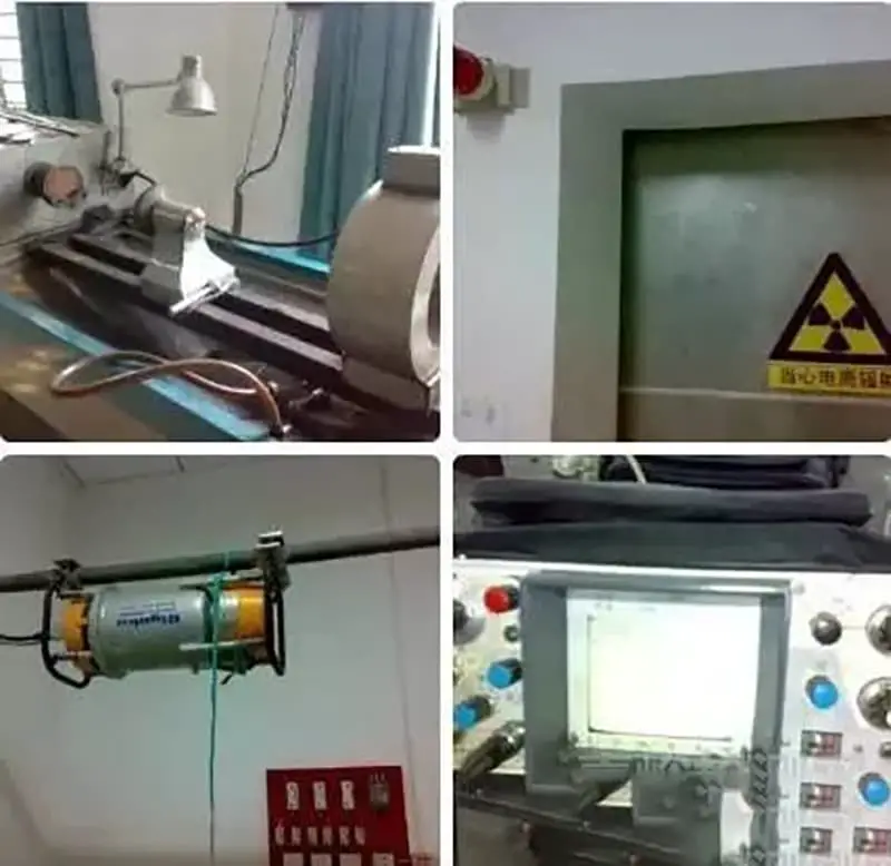
In the figure below:
- From left in the first row: Stationary Magnetic Particle Detector;
- Second from left in first row: Radiographic Examination Room Protective Shield Door.
- From left to second row: Portable x-ray tube;
- Second from left in second row: Analog ultrasonic flaw detector with type A display.
Radiography, a non-destructive testing method, uses x-rays produced by x-ray tubes or gamma rays produced by radioactive isotopes to penetrate the workpiece, with the film serving as the recording medium. This method is the most basic and widely used radiographic testing method, and is also the main content of professional RT training.
2. Principle 1 of Radiography:
Radiographic testing essentially uses the energy of electromagnetic waves or radiation (X-rays and gamma rays). The rays interact with the material during penetration, causing their intensity to decrease due to absorption and scattering. The degree of intensity attenuation depends on the attenuation coefficient of the material and the thickness penetrated by the rays.
3. Principle 2 of Radiography:
If a defect exists in a specific part of the radiographed object (workpiece), and the attenuation coefficient of the material constituting the defect is different from that of the sample (for example, in a weld seam, the air in a porosity defect has a much lower attenuation coefficient than steel), the intensity of the beam transmitted from that local area will be different from its surroundings.
By placing the film in a suitable position to be exposed to the transmitted rays, a negative is obtained after processing in a darkroom.
After the rays penetrate the workpiece, due to the different intensities of the rays transmitted between the defective and intact parts, the corresponding parts on the film will have different degrees of darkness.
Radiographic inspectors can identify the location and nature of the defect by observing differences in the darkness of the film. The basic principles described above are similar to those for taking x-rays in a hospital.
4. Radiography Characteristics
(1) Scope of Application
Radiography is suitable for butt joints of various fusion welding methods (arc welding, gas shielded welding, slag welding, gas welding, etc.), can also inspect cast steel parts, and under special circumstances , can be used to inspect corner welds or other special structural parts.
(2) Advantages of Radiography
a) Direct visualization of defects: Radiography uses film as a recording medium, the nature, quantity, size and location of defects can be accurately determined by observing the film.
b) Easy detection of defects that cause local differences in thickness: It has a high detection rate of defects such as porosity and slag inclusion.
c) Radiography can detect length and width dimensions on the order of millimeters and submillimeters, or even less, and there is practically no lower limit of detection thickness.
d) Almost applicable to all materials, it can achieve good results on metals such as steel, titanium, copper and aluminum. This method does not require rigid shapes, surface roughness of the sample, and the grain size of the material does not affect it.
(3) Limitations of Radiography
a) The detection rate of crack-like defects is affected by the radiographic angle and cannot detect thin-layer defects perpendicular to the radiation direction, such as delamination in steel plates.
b) The upper limit of detection is limited by the penetrating power of the rays, for example, a 420 kv x-ray machine can penetrate a maximum steel thickness of approximately 80 mm, and gamma rays from a radioactive isotope of Cobalt- 60 (Co60) can penetrate a maximum steel thickness of approximately 150mm. For thicker parts, special equipment is required – accelerators, which can penetrate thicknesses greater than 400 mm.
c) It is generally not suitable for testing steel plates, steel pipes, forgings, and is rarely used for inspection of joints in brazing, friction stir welding and other welding methods.
d) Radiography has higher testing costs and slower testing speed.
e) Radiation is harmful to the human body, protective measures are necessary.
2. Ultrasonic Testing (UT)
Ultrasonic testing (UT), commonly abbreviated as UT, is the most widely used, frequently applied and rapidly developing technology in the field of non-destructive testing.
It serves multiple purposes in quality control during product manufacturing, raw material inspection, and process improvement. It is also an indispensable tool in equipment maintenance.
Ultrasonic testing (UT) is a non-destructive testing method widely used in various industries.
When an ultrasonic wave enters an object and encounters a defect, a portion of the wave is reflected.
By analyzing the reflected wave using a transmitter and receiver, the defect can be accurately measured. The location and size of the internal defect can be displayed and the material thickness can be determined.
1. Ultrasonic Testing Applications
The main applications of ultrasonic testing are detecting macroscopic defects within workpieces and measuring material thickness.
2. Ultrasonic inspection classification
Ultrasonic testing can be categorized into several methods based on different characteristics:
(1) Classification by principle: Ultrasonic pulse reflection method, time-of-flight diffraction (TOFD), etc.
(2) Classification by display mode: Type A Screen, Ultrasonic Image Screen (B, C, D, P Scan Image, Dual Control Matrix Image, etc.).
3. Principle of ultrasonic testing
Ultrasonic testing essentially depends on the interaction between ultrasonic waves and materials: reflection, refraction and diffraction.
(1) What is an ultrasonic wave?
We refer to mechanical waves that can cause auditory sensation as sound waves, with frequencies between 20-20,000 Hz. Mechanical waves with frequencies above 20,000 Hz are known as ultrasonic waves, which are inaudible to humans. For the inspection of metals such as steel, we typically use ultrasonic waves with frequencies ranging from 0.5 to 10MHz. (1MHz=10^6Hz)
(2) How are ultrasonic waves emitted and received?
The main component of the ultrasonic test probe is a piezoelectric crystal, which has the piezoelectric effect: under alternating compressive and tensile stress, the crystal can produce an alternating electric field.
When a high-frequency electrical pulse excites the piezoelectric crystal, it triggers the reverse piezoelectric effect, converting electrical energy into acoustic energy (mechanical energy).
The probe intermittently emits pulse-shaped ultrasonic waves, known as pulse waves. When the probe receives ultrasonic waves, it triggers the direct piezoelectric effect, converting acoustic energy back into electrical energy.
The conventional probe used in ultrasonic testing generally consists of a piezoelectric crystal, damping block, connector, cable, protective film and housing. It generally falls into two categories: straight probe and angled probe. The latter usually includes a wedge to tilt the crystal at a certain angle with respect to the incident surface.
The following image is a structural diagram of a typical angle probe.

The following image is a physical image of an angled probe:

The probe model is 2.5P812 K2.5, its parameters are:
a) 2.5 represents the frequency f: 2.5MHz;
b) P indicates that the crystal material is lead zirconate titanate ceramic, which has the advantages of good temperature stability, excellent electrical properties, easy manufacturing and low cost;
c) 812 indicates that the size of the rectangular crystal is: 8mm*12mm;
d) K2.5 indicates: the tangent of the refraction angle of the angled probe is 2.5, that is, tan(68.2°)=2.5, and its refraction angle is 68.2°.
Working principle of Type A display ultrasonic pulse reflection method
The pulse wave generated by the sound source enters the workpiece, and the ultrasonic wave propagates forward into the workpiece in a certain direction and speed. When encountering an interface with different acoustic impedances on both sides (generally due to some discontinuity in the material, such as cracks, pores, inclusions, etc.), a part of the sound wave is reflected.
The testing equipment receives and displays: The amplitude and position of the sound wave are analyzed to assess whether a defect exists or the size and location of the existing defect.
Characteristics of Type A display ultrasonic pulse reflection method
Scope of application
It is applicable to various parts made of metals, non-metals and composite materials.
a) Inspection of raw materials and components: steel plates, steel forgings, aluminum and aluminum alloy plates, titanium plates and titanium alloys, composite plates, seamless steel tubes, etc.
b) Inspection of butt welding joints: steel butt joints (including pipe seat angle welds, T-shaped welding joints, supports and structural parts), aluminum and aluminum alloy butt joints.
The following picture is a steel butt joint: T-shaped welding joint.

Advantages of ultrasonic pulse reflection method with Type A display
a) Strong penetration capacity, capable of detecting internal defects in parts with a wide range of thicknesses. For metal materials, it can inspect thin-walled tubes and plates with a thickness of 1 to 2 mm, as well as steel forgings several meters long.
b) Precise location of the defect.
c) High detection rate for area-type defects.
d) High sensitivity, capable of detecting very small defects inside the part. The theoretical sensitivity of ultrasonic testing is about half of the ultrasonic wavelength. For steel parts inspected with an angular ultrasonic probe of 2.5 MHz frequency, the sensitivity is about 0.65 mm.
e) Low inspection cost, fast speed, portable equipment, harmless to humans and the environment, convenient for on-site use.
Limitations of Type A display ultrasonic pulse reflection method
a) More studies are necessary to accurately qualify and quantify defects in the parts.
b) It is difficult to perform ultrasonic testing on parts with complex shapes or irregular external shapes.
c) The position, orientation and shape of the defect have a certain impact on the test results.
d) The material and grain size of the part greatly affect the test.
e) The test results are not intuitive and there is no direct witness record of the test results.
4. Advantages of Ultrasonic Testing:
- It has a high penetration capacity; for example, it can effectively detect steel to a depth of more than 1 meter.
- It has high sensitivity to detect planar defects such as cracks and interlayers, and can measure the depth and relative size of defects.
- The equipment is portable, safe to operate and easy to use for automatic inspection.
5. Disadvantages:
Inspecting a complexly shaped workpiece is challenging, especially when the surface being inspected requires a certain degree of finish. To ensure complete acoustic coupling, a coupling agent must be used to fill the space between the probe and the surface being inspected.
3. Magnetic Particle (MT) Test
To begin, let's understand the principle behind magnetic particle testing.
When ferromagnetic materials and workpieces are magnetized, the presence of discontinuity causes the magnetic lines of force on and near the surface of the workpiece to become locally distorted, creating a magnetic leakage field. This field attracts magnetic particles that are applied to the surface of the part, resulting in visible magnetic marks that reveal the position, shape and size of any discontinuities when viewed under adequate lighting.
Magnetic Particle Testing (MPT), commonly abbreviated as MT by industry experts, is a well-established non-destructive testing method. It finds wide application in various fields such as aerospace, armament, shipbuilding, railways, automotive, oil and gas, chemical industry, boiler pressure vessels and pressure piping.
The main application of magnetic particle testing is to detect macroscopic geometric defects on the surface and near the surface of ferromagnetic parts, such as surface porosity and cracks.
1. Magnetic particle inspection methods
Based on different characteristics, magnetic particle testing can be divided into several methods:
(1) According to the application time of magnetic particles, it can be divided into: Continuous Method and Residual Method.
a) Continuous Method: Application of magnetic powder while magnetizing the part.
b) Residual Method: First magnetizing the part, and after stopping the magnetization, the residual magnetism of the part is used, followed by the application of magnetic powder.
(2) Based on the display materials, it can be divided into: Fluorescent Method and Non-Fluorescent Method.
a) Fluorescent Method: Use of fluorescent magnetic powder to observe magnetic traces under a black light lamp.
b) Non-Fluorescent Method: Uses common black or red magnetic powder to observe magnetic traces under normal lighting conditions.
(3) According to the magnetic powder carrier, it can be divided into: Wet Method and Dry Method.
a) Wet method: The magnetic powder carrier is liquid (oil or water).
b) Dry Method: Applied directly in the form of dry powder to the piece, this method is only used in special circumstances.
For example, magnetic particle inspection of pressure vessel welds would generally employ: Wet Method + Non-Fluorescent Method + Continuous Method. This means that we will disperse the black or red magnetic powder in a water or oil carrier (i.e. magnetic suspension) under normal lighting conditions and apply the magnetic suspension while magnetizing the weld, observing the formation of magnetic traces simultaneously.
Below is a typical application of the Wet Method + Non-Fluorescent Method + Continuous Method in magnetic particle inspection. The process involves magnetization via a crossed magnetic yoke machine, combined with black magnetic powder.
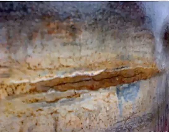
The following diagram illustrates the detection of crack defects using magnetic particle inspection on the circumferential butt weld of a spherical tank. The magnetic traces are large and clear.
The image below shows a butt weld pipe. The magnetic traces are not as apparent as in the previous image. Can you still identify them?

2. Magnetic particle inspection principle
Magnetic particle inspection essentially utilizes changes in the magnetism of the material.
When a ferromagnetic part is magnetized, if the material of the part is continuous and uniform, the magnetic induction lines in the part will be largely confined within the part, with almost no magnetic induction lines leaving or entering the part from the inspected surface, resulting in no significant leakage magnetic field. As shown below:

(1) No leakage magnetic field
When there are discontinuities on the surface of the part that cut the magnetic lines of force, due to the low magnetic conductivity and high magnetic resistance of the discontinuous parts, the magnetic induction lines will change their paths.
Most of the altered path magnetic flux will pass through the workpiece from the bottom of the magnetic resistance discontinuity.
When the magnetic induction intensity of the workpiece is relatively high, the bottom of the workpiece at the discontinuity cannot accept more magnetic flux, or when the size of the discontinuity is large, some magnetic flux will escape from the discontinuity and cross the top of discontinuity before re-entering the workpiece.
This leakage of magnetic flux will cause parts on both sides of the discontinuity to polarize, forming a so-called leakage magnetic field. As shown below:

(2) Existing Leakage Magnetic Field
Basic principle of magnetic particle inspection: After magnetization of the workpiece, if there are discontinuities (such as cracks) on the surface and near the surface of the workpiece, a leakage magnetic field (i.e. leakage magnetic field) will form on the surface of the discontinuous parts.
By attracting and gathering the magnetic particles applied during the inspection process through the leak magnetic field, magnetic traces are eventually formed, which can provide a display of the location, shape and size of the defect.
3. Features of Magnetic Particle Inspection
(1) Scope of Application
Magnetic particle inspection can be used to inspect raw materials and semi-finished products such as sheets, profiles, tubes and forgings. It can also be used for final and in-process inspection of forged steel parts, welded parts and cast steel parts during manufacturing. Furthermore, it can be used for in-service inspection of important machines, pressure vessels, oil storage tanks and other industrial facilities.
(2) Advantages of Magnetic Particle Inspection
a) It provides an intuitive display of the shape, location, size and severity of the defect and can approximately determine the nature of the defect.
b) It has high sensitivity. The magnetic traces formed by the accumulation of magnetic particles in defects have an amplifying effect. It can detect a minimum defect width of approximately 0.1 μm and discover microcracks of approximately 10 μm in depth.
c) It has good adaptability, is almost unlimited by the size and shape of the test part, and through the comprehensive adoption of various magnetization methods, defects in all directions of the part can be detected.
d) The inspection speed is fast, the process is simple, the operation is convenient, the efficiency is high, and the cost is low.
(3) Limitations of Magnetic Particle Inspection
a) It can only be used to inspect ferromagnetic materials such as carbon steel and structural alloy steel, and cannot be used to inspect non-ferromagnetic materials such as magnesium, aluminum, copper, titanium and austenitic stainless steel.
b) It can only be used to detect surface and near-surface defects and cannot detect defects buried too deeply. The buried depth of detectable underground defects generally does not exceed 1~2mm.
c) It is difficult to quantitatively determine the depth of burial of the defect and the height of the defect itself.
d) Visual inspection method is commonly used to check defects. Judging and interpreting magnetic traces requires technical experience and quality.
It can be challenging to identify shallow scratches on the surface, deep holes that are buried, and delamination and folds at an angle of less than 20° to the surface of the part.
4. Penetration Test (PT)
Penetrant Testing (PT), one of the earliest Non-Destructive Testing (NDT) methods in industry, is widely used in various fields of modern industry due to its simplicity and ease of operation.
1. Penetration Testing Applications
It is used to inspect surface opening defects, such as surface cracks, on metallic (steel, aluminum alloy, magnesium alloy, copper alloy, heat-resistant alloy, etc.) and non-metallic (plastic, ceramic, etc.) parts. .
During the manufacture and operation of industrial products, surface cracks with a width of several micrometers may occur. Studies in fracture mechanics have shown that, under adverse working conditions, these small cracks can be sources of equipment failure.
2. Penetration Test Methods
Based on different characteristics, Penetrant Testing can be divided into several different methods:
By display materials, it can be divided into fluorescent and non-fluorescent methods. The former is called the “Fluorescent Penetrant Test” and the latter is called the “Color Penetrant Test”.
A typical schematic diagram of defects in fluorescent penetration tests.

Microcracks invisible to the naked eye become especially noticeable as yellowish-green fluorescence under the irradiation of a UV lamp after the fluorescent penetration test, as shown in the diagram below:
3. Principle of Penetration Testing
The penetrant test fundamentally uses the surface energy of liquids.
When a liquid comes into contact with a solid interface, one of the following three phenomena occurs, with θ denoting the contact angle, as illustrated below:

(a) θ=0°, complete wetting;
(b) θ<90°, partial wetting;
(c) θ>90°, no wetting.
For a given liquid, the lower the surface tension, the less work is required to overcome this force as the liquid spreads across the interface, resulting in better wetting.
—Surface tension is the tension acting along the surface of any boundary line caused by unbalanced molecular forces in the surface layer of the liquid.
Hair Phenomenon:
This is observed when a liquid wets a capillary tube or an object with tiny gaps, and the liquid flows along these tiny gaps.
If a liquid can wet a capillary tube, the liquid rises up the tube. The smaller the internal diameter of the pipe, the higher the water level inside it. For example, water rises inside a glass capillary tube, similar to water penetrating the capillary.
If a liquid cannot wet a capillary tube, the liquid level decreases in the tube. For example, mercury (Hg) inside a glass capillary tube causes the liquid level to drop.

Basic Principle of Penetration Testing:
Due to the capillary phenomenon, when people apply a penetrant containing fluorescent or colored dyes to the surface of a test piece, the penetrant penetrates many small open defects on the surface (small openings are similar to capillaries, and the penetrant penetrates small defects is similar to the wetting phenomenon). After removing excess penetrant adhering to the surface of the test piece and drying, developers are applied. Under capillary action, the penetrant in the defects is reabsorbed onto the surface of the test piece, creating an amplified display of the defects. Visual inspection can then be used to observe the shape, size and distribution of defects.

4. Features of penetration testing
- Forms
Penetration testing can be applied to detect surface defects in a variety of metallic and non-metallic materials, both magnetic and non-magnetic. With the exception of porous materials, which are difficult or impossible to test, this method can be used on virtually any material to identify surface defects, producing satisfactory results.
- Advantages of Penetration Testing
(a) It is not limited by the magnetic properties, shape, size, structural composition, chemical composition, or defect orientation of the part being tested. A single operation can detect defects in all directions.
(b) The operation is simple and the equipment is straightforward.
(c) Defect display is intuitive and highly sensitive.
- Limitations of Penetration Testing
(a) It can only detect surface defects in materials. For hidden defects in materials, penetration testing is powerless. It should be noted that due to the difficulty of interpreting images of defects in porous materials, penetration testing is not suitable for surface defects in these materials.
(b) Penetrant components can be corrosive to the test piece, therefore strict control of trace elements such as sulfur and sodium is necessary.
(c) The organic solvents used in penetrants are volatile and industrial dyes can be toxic, requiring protective measures against inhalation.
5. X-ray test
Radiographic testing is used because x-rays are absorbed differently by different substances and thicknesses, resulting in varying intensities of x-rays passing through the irradiated object.
When the negative film is placed on the opposite side of the irradiated object, corresponding graphics are generated due to the different X-ray intensities.
Based on the resulting images, the film evaluator can determine whether there are defects inside the object and the nature of those defects.
Applicability and limitations of radiographic tests:
- It is sensitive in detecting volumetric defects and facilitates defect characterization.
- Radiographs are easy to retain and track.
- They provide visual display of the shape and type of defects.
- However, there are limitations to this method as it cannot determine the buried depth of defects and has a limited detection thickness. Furthermore, negatives require special washing, which is harmful to the human body and can be expensive.
6. Eddy Current Testing (ET)
Eddy Current Testing (ET) occupies a significant position in the field of Non-Destructive Testing (NDT). It plays an increasingly important role in various sectors, such as aerospace, metallurgy, machinery, electrical power, chemical industry and nuclear energy.
1. Eddy current testing applications
This method is used to detect macroscopic geometric defects on the surface and near the surface of conductive metallic materials, as well as for coating thickness measurement.
2. Eddy current testing methods
Based on different characteristics, eddy current testing can be divided into several methods:
1) Classification by test coil shape:
a) External type: The test sample is placed inside the coil for testing, suitable for detecting defects in the outer wall of tubes, rods and wires.
b) Internal type: The test is carried out inside the tube, specifically to inspect defects on the inner wall of thick-walled tubes or drilled holes.
c) Probe type: Placed on the surface of the sample for testing, suitable not only for large-diameter plates, rods and tubes of simple shape, but also for mechanical parts of complex shape.
2) Classification by test coil structure:
a) Absolute method: The coil consists of a single coil.
b) Differential method: Consists of two coils connected oppositely.
c) Self-comparison method: Multiple coils are wound around a single frame.
d) Standard comparison method: Wrapped around two frames, one coil contains a standard sample, the other is used for actual testing.
3) Classification by electrical connection of the test coil:
a) Self-induction method: The test coil uses a single winding for excitation and detection.
b) Mutual induction method: The excitation winding and the detection winding are separated.
c) Type of parameter: The coil itself is a component of the circuit.

3. Eddy current test principle:
The essence of eddy current testing is the use of the principle of electromagnetic induction.
Regardless of the cause, any change in the magnetic flux passing through the closed circuit will generate a current in the circuit. This phenomenon of exciting a current due to changes in the magnetic flux in the loop is called electromagnetic induction, and the current produced in the loop is called induced current.
The circuit contains two mutually coupled coils. If alternating current is applied to the primary coil, an induced current is generated in the secondary coil under the action of electromagnetic induction. On the other hand, the induced current will affect the relationship between current and voltage in the primary coil, as shown in the figure below.
4. Eddy current test features:
- Application range:
a) Process Inspection and Final Product Testing: Quality control during the manufacturing process, or elimination of defective finished products.
b) In-service inspection: Regular inspection of mechanical components and heat exchange tubes, etc.
c) Other Applications: Measurement of thickness of metal sheets and coatings, classification of materials and measurement of electrical conductivity, etc.
- Advantages of eddy current testing:
a) The inspection does not require contact with the part or coupling agent and can be carried out at high temperatures. Meanwhile, the probe can be extended to remote areas for inspection, effectively inspecting narrow areas and deep walls of the workpiece.
b) It has high sensitivity for detecting surface and near-surface defects.
c) Efficient, high-speed automated inspection of tubes, rods and wires is easy to achieve. Inspection results can be processed digitally and then stored, reproduced and the data processed.
- Limitations of Eddy Current Testing:
a) It is only applicable to the inspection of conductive metallic materials or non-metallic materials that may induce eddy currents.
b) It is only suitable for detecting surface and near-surface defects of the workpiece and cannot detect deep internal defects of the workpiece.
c) There are many factors that affect the effect of eddy currents. Currently, the qualitative and quantitative identification of defects is still relatively challenging.
Concluding
In summary, ultrasound and X-ray flaw detection are effective for detecting internal defects. Ultrasonic waves are suitable for parts with regular shapes above 5 mm. However, X-rays cannot locate the depth of defects and involve radiation.
Magnetic particle and penetrant testing are useful for detecting surface defects in tested parts. Magnetic particle inspection is limited to detecting magnetic materials, while liquid penetrant inspection is only suitable for detecting surface opening defects.