With the rapid development of the manufacturing industry, driven by the national clean energy policy, the demand for coal, hydropower, nuclear and wind power has increased, along with the need for large plate rolling machines to process pipeline and column tower parts .
The offshore oil and gas, petrochemical, coal chemical, and heavy high-pressure vessel production industries have become more prevalent, leading to the widespread use of specialized heavy plate rollers in the rolling of thick, high-strength plates, including 1,000 ton hydrogenation reactors, 2,000 ton coal liquefaction reactors and 10,000 m reactors 3 spherical natural gas tanks.

Working Principle of 3 Roll Bending Machine
Activate JavaScript

Roll Bending Machine, also known as Round or Roll Machine, is a versatile forming equipment used to roll metal plates into cylinders, cones, curves and other shapes.
This machine works using the principle of three-point forming circles, where the relative position change and rotational movement of the work rolls cause continuous plastic deformation of the sheet metal, resulting in the desired shape of the part.
Roll bending machine is widely used in industries such as boiler manufacturing, shipbuilding, petroleum, chemicals, metal structures and machine manufacturing.
In a typical 3-roll press brake, two lower rolls serve as live rolls and can rotate in positive and reverse directions, while the upper roll serves as a follower roll, which can move up and down vertically. (See figure)

- Movable Rolling Seat
- Hydraulic cylinder
- Left frame
- Base
- Top roller
- Bottom roller
- Tie rod
- Right frame
- Hydraulic cylinder
- Fixed rolling seat
- roller gear
- Reducer
- Motor
- Unloading device
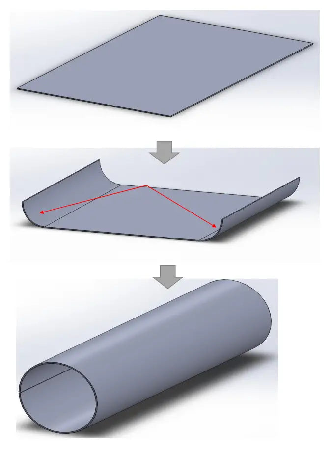
The steel sheet rolling process involves placing the sheet between upper and lower rollers. The three cutting points exposed to the sheet metal by the three rollers cause the sheet to bend into a curved or circular shape.
This sheet metal forming process can be viewed as a continuous three-point bending process carried out by the three-roll bending machine.
One end of the metal plate is fed into the machine between the upper and lower rollers.
The upper roller then applies downward pressure on the metal plate, causing it to undergo plastic flexural deformation due to compression.
The rotation of the lower rollers, driven by friction between the plate and the rollers, causes the plate to move back and forth along its longitudinal direction.
The upper roller continues to exert downward pressure and moves back and forth across the plate.
As the plate passes through the roll deformation zone, plastic deformation occurs when the stress exceeds the yield strength.
This causes the plate to undergo plastic deformation through bending along its entire length and is molded into the desired shape.
By adjusting the relative position between the upper and lower rollers, the plate can be bent to a radius no less than that of the upper roller.
A diagram of the working principle of a symmetrical three-roll bending machine is given below.

Driven rollers II and III are driven by a motor and a reducer and rotate in the same direction (or opposite directions) at the same speed.
Due to the friction between the rollers and the plate, the plate advances as the rollers rotate.
By adjusting the position of the upper roller, plates of varying curvatures can be produced.
If the part does not achieve the desired curvature after a single rolling process, the upper roller can be adjusted and the process repeated until the desired shape is achieved.
The three rollers of the symmetrical three-roll bending machine are arranged in an isosceles triangle, causing the two ends of the workpiece to leave a straight line segment in the rolling process.
This straight line segment, which is about half the distance between the centers of the two lower rollers, is where the roller cannot roll and is the main disadvantage of this type of machine.
Despite its limitations, the three-roll symmetric plate calender is widely used due to its simple structure, ease of operation and low cost.
The line segment problem can be solved by different methods, depending on the specific situation, as shown in the table below.
| Item | Solution |
| Elbow pre-flexion | This technique involves using a die to pre-bend the ends of the steel sheet in a press to obtain the desired curvature. |
| Keep the allowance | Add the appropriate board margin to the ends of the board. After extending a certain length at both ends, the remainder (also known as a straight line segment) can be cut. |
| Add base plate for prebending | This method is carried out in the rolling mill, as shown in figure 3b.
However, when adopting this method, it is essential to take into account the capacity of the rolling mill, i.e., the combined bending force of the part and the required gasket must not exceed that of the rolling mill. |

For another three-roll asymmetric press brake, the spindle roll arrangement is designed to eliminate straight line segments in the rolled part.
The machine has the feature that the two lower rollers can be adjusted vertically. One lower roller can be adjusted to match the center distance of the upper roller, while the other is raised to the appropriate position.
The leading end of the steel plate can be bent and rolled. After half a roll, the alignment of the two lower rolls is changed and rolling continues to eliminate the straight line segment at the end of the part.
Alternatively, the workpiece can be turned so that the back end becomes the front end for rolling, which will also eliminate the line segment.
3 Roll Press Brake Machine Lamination Process
Here is a brief overview of the rolling process of a short cylinder with a diameter of 400 mm or greater, to help you understand the operation of a three-roll press brake.
Getting the material
The material must be checked in accordance with the design and process requirements, and must not have obvious defects on its surface.
Material quality and specifications must comply with relevant national and industry standards.
Draw the line
When expanding, the diameter of the cylinder must correspond to the actual diameter of the final shell, and the diameter of the cylinder material must be calculated based on the intermediate diameter of the cylinder.
The expansion direction must be aligned with the rolling direction of the steel and limited to a 45° position. The layout must be efficient, utilizing edge material effectively and increasing steel utilization.
If the cylinder is constructed from multiple sections, welding must be performed appropriately in accordance with the technical requirements for assembly and welding of the equipment.
The spacing between the end casing butt welds and the longitudinal weld the seams of the cylindrical section of the casing must be greater than 3 times the thickness of the cylinder and not less than 100 mm.
If the cylinder is connected to a pipe, support, reinforcing ring, base plate, etc., the interposition of the longitudinal and circumferential welds on the cylinder must avoid puncturing the weld bead or being too close to it, and the reinforcing ring or the base plate must cover the weld seams.
Line drawing must be accurate, using a geometric mapping method to draw a vertical line, bisector, and midpoint rather than a master square.
Leave the necessary margins, first draw the edge cutting line on the metal plate, then the actual material line and check the line.
Tolerance requirements for drawing lines for blanking:
The tolerance requirement for drawing cylinder height H is H ± 1 mm.
The difference between two diagonal lines (△L = L1 – L2) should be less than or equal to 2mm, and the cylinder section length tolerance is L ± 3mm.
The perimeter formula is L = π (Di + S), where Di is the diameter of the cylinder (mm) and S is the thickness of the cylinder (mm).
After marking, the material marking is transplanted into the 100mm x 100mm box in the upper right corner of the steel sheet.
Edge suppression and processing:
For carbon steel sheets with a thickness of less than 12 mm, cutting is carried out with a cutting machine if possible (otherwise, a semi-automatic cutting machine is used).
After cutting, the slag must be cleaned and deburred.
For sheets thicker than 6mm that require grooves, semi-automatic cutting machines or chamfering machines are used. For sheets with a thickness of less than 6 mm, the grinding method must be used.
The grooves generated by the flame cutting machine must have clean slag, and the welding groove must not have flaws such as cracks or delamination.
Before welding, the surface of the welded joint must be cleaned of any harmful impurities such as oxide, grease and slag.
The clearance range (calculated from the groove or edge of the plate) must be ≥ 20mm.
Pre-bending
When rolling a plate, the ends of the plate may be bent due to lack of contact with the upper roller, resulting in residual straight edges.
During symmetrical bending, the residual straight edge is normally about half the center distance of the bottom roll and depends on the plate thickness.
Asymmetric bending results in residual straight edges that are approximately 1/6 to 1/10 of those of symmetric bending.
These residual straight edges can be difficult to eliminate completely during correction and can lead to quality problems and equipment accidents, so they must be pre-bent.
If pre-bending is not possible, they can be corrected using a template after final lamination.
Before bending, the surface of the steel plate and the surface of the roller must be cleaned and any rust, leather, wool, edges, corners or hard particles must be removed.
For example, in stainless steel rolling, the upper and lower rolls must be protected by wrapping them with adhesive tape or a special paint layer, and the protective layer must not contain hard particles.
Center alignment
When the plate is inserted into the rolling mill, to avoid misalignment, the part must be rotated and the main axis of the part must be aligned parallel to the roller axis to ensure that the round rolling is of good quality.
Rolling Circles
Circular rolling is the main step in product formation and can be carried out in single-pass or multiple-pass processes.
The number of passes depends on process requirements, such as the maximum allowable strain rate in cold rolling, and equipment limitations, such as adhesion and power conditions.
A certain amount of over-rolling should be applied when the springback in cold rolling is significant.
The longitudinal offset of the cylinder end must be less than 1.5 mm. The plate lamination process is shown in the attached figure.

Rounding correction
The purpose of rounding correction is to make the curvature of the entire circle as uniform as possible, thus improving the quality of the product. Typically, the steps are:
(1) Feeding: Based on experience or calculation, the rollers can be adjusted to the correct maximum curvature position.
(2) Round Rolling: Roll the cylinder twice under correction curvature, focusing on the welding position to obtain a consistent curvature around the entire circle.
(3) Unloading: Gradually decrease the load, allowing the part to be rolled several times under reduced correction load.


