1. Servo motor pulse control mode
In some small stand-alone equipment, selecting pulse control to perform motor positioning should be the most common application mode.
This control mode is simple and easy to understand.
Basic control idea: the total amount of pulse determines the displacement of the motor, and the frequency of the pulse determines the speed of the motor.
The pulse is selected to realize servo motor control.
Open the servo motor manual and you will see the following table:
| Command pulse form | Signal name | Positive direction command | Negative direction command |
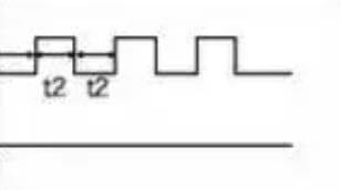
| 90-bit phase difference
Biphasic pulse phase A + B |
PULSE SIGNAL |
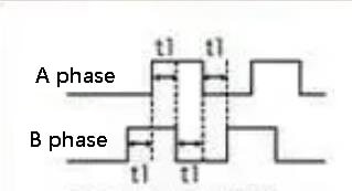
B is 90 degrees faster than phase a |
B is 90 degrees slower than phase a |
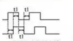
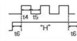
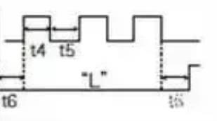
| Positive pulse train + negative pulse train | PULSE SIGNAL |
|
|
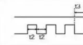
| Pulse + symbol | PULSE SIGNAL |
|
|
Both are pulse controlled, but the implementation method is different:
First, the driver receives two (a, b) high-speed pulses and determines the direction of rotation of the motor through the phase difference of the two pulses.
As shown in the figure above, if B is 90 degrees faster than phase a, it is positive rotation; If B is 90 degrees slower than phase a, it will be reversed.
During operation, the two-phase pulses of this control alternate, which is why we also call this control method differential control.
It has different characteristics, which also shows that this control mode has greater anti-interference ability.
In some application scenarios with strong interference, this mode is preferred.
However, in this way, the motor shaft needs to occupy two high-speed pulse ports, which is not applicable to the high-speed pulse port voltage.
Second, the driver still receives two high-speed pulses, but the two high-speed pulses do not exist at the same time.
When one pulse is in the output state, the other must be in the invalid state.
When selecting this control mode, we must ensure that there is only one pulse output at the same time.
Two pulses, one output in the positive direction and the other in the negative direction.
As in the case above, this mode is also a motor axis, which needs to occupy two high-speed pulse ports.
Third, only one pulse signal needs to be given to the driver, and the forward and reverse operation of the motor is determined by the unidirectional IO signal.
This control method is simpler to control, and the resource occupation of the high-speed pulse port is minimal.
In general, small systems this method may be preferred.
2. Servo motor analog control mode
In the application scenario where the servo motor needs to be used to realize speed control, we can select the analog quantity to control the motor speed.
The value of the analog quantity determines the operating speed of the motor.
The analog quantity can be selected in two ways: current or voltage.
Voltage Mode:
You just need to add a certain voltage to the end of the control signal.
In some scenarios, you can even use a potentiometer to perform the control, which is very simple.
However, when voltage is selected as the control signal, in complex environments, the voltage is easily disturbed, resulting in unstable control.
Current mode:
A corresponding current output module is required, but the current signal has strong anti-interference ability and can be used in complex scenes.
3. Servo motor communication control mode
Common ways to realize servo motor control by communication include CAN, EtherCAT, MODBUS and PROFIBUS.
Using communication to control the motor is the preferred control method in some large-scale and complex system application scenarios.
In this way, the system size and number of motor shafts are easy to cut and there is no complex control wiring. The constructed system has high flexibility.
4. Expansion
1. Servo motor torque control
Torque control mode is for setting the external output torque of the motor shaft via external analog quantity input or direct address assignment.
For example, if 10V corresponds to 5nm, when the external analog quantity is set to 5V, the motor shaft output is 2.5nm.
If the motor shaft load is less than 2.5 nm, the motor rotates forward, the motor does not rotate when the external load is equal to 2.5 nm, and the motor reverses when it is greater than 2.5 nm (generally under gravity load).
The set torque can be changed by changing the analog quantity setting in real time or by changing the corresponding address value through communication.
It is mainly used in winding and unwinding devices that have strict requirements on the tension of materials, such as winding devices or optical fiber pulling equipment.
The torque setting should be changed at any time according to the change of winding radius, so as to ensure that the tension of materials will not change with the change of winding radius.
2. Servo motor position control
In position control mode, the rotation speed is generally determined by the frequency of external input pulses, and the rotation angle is determined by the number of pulses.
Some servos can assign speed and displacement values directly through communication.
Because position mode can strictly control speed and position, it is generally used in positioning devices, CNC machine tools, printing machines and so on.
3. Servo motor speed mode
The rotation speed can be controlled via analog quantity input or pulse frequency.
When there is external loop PID control of the upper control device, the speed mode can also be positioned, but the motor position signal or the direct load position signal must be returned to the upper computer for operation.
Position mode also supports direct load outer ring to detect position signal.
At this time, the encoder at the motor shaft end only detects the motor speed, and the position signal is provided by the direct sensing device at the end load end.
This has the advantage that it can reduce the error in the intermediate transmission process and increase the positioning accuracy of the entire system.
4. About the third loops
The servo is generally controlled by three loops. The so-called three-loop are three closed-loop negative feedback PID regulation systems.
The innermost PID loop is the current loop that is completely realized within the servo driver.
The output current of each phase from the driver to the motor is detected through the Hall device, and the negative feedback is adjusted to the current for PID adjustment, so that the output current is as close as possible to the set current.
The current loop controls the motor torque, so the driver calculation is the lowest in torque mode and has the fastest dynamic response.
The second loop is the speed loop.
Negative feedback PID adjustment is performed using the signal detected in the motor encoder.
Its PID output in the loop is directly the current loop adjustment. Therefore, speed loop control includes speed loop and current loop.
In other words, the current loop must be used for any mode, and the current loop is the basis of control.
At the same time as controlling speed and position, the system controls current (torque) to achieve corresponding control of speed and position.
The third loop is the position loop, which is the outermost loop.
It can be built between the driver and the motor encoder, or between the external controller and the motor encoder or the end load, depending on the actual situation.
Since the internal output of the position control loop is the adjustment of the speed loop, the system performs the operation of all three loops in the position control mode.
At this time, the system has the largest amount of operation and the slowest dynamic response speed.