1. Selection, replacement and precautions for upper and lower die is
1 ) Selection of the upper punch
A) The choice of the upper punch for the press brake is determined by the bending force and must not exceed the maximum load capacity of the die.
B) If a special die is selected, it is crucial to note that the load on these dies differs from that on a standard die.
2 ) Lower matrix selection
The width of the V-shaped opening in the bottom die must be determined based on the thickness (S) of the sheet material. The formula is as follows:
If S<3mm, the width of the V-shaped opening should be between 6 to 8 times the thickness of the material (V = (6~8) × S).
If S>3mm, the width of the V opening should be between 8 to 12 times the thickness of the material (V = (8~12) × S).
Where:
- S = sheet thickness (mm)
- b = minimum fold width (mm)
- V = width of the lower die opening (mm)
Note that the minimum bend width (b) and bend angle must be adjusted accordingly to scientifically determine the shape limits of the bottom die.
2. Precautions for installing upper and lower molds and installation methods
Activate JavaScript

(1) Precautions
A) The operator must observe safety principles when installing the mold in the hazardous area of the press brake.
B) It is not permitted to pass the hand or body through the mold.
(2) Upper Mold Installation
A) Switch the machine control mode to manual mode using the ignition key.
B) Activate manual control in manual mode.
C) Press the machine spindle start button.
D) Step on the pedal and let the press brake ram slowly descend until it stops at the curvature conversion point.
E) Press the machine axis stop button.
F) Loosen the die clamps to install or replace the upper punch.
G) Fix the upper mold and upper mold base and lightly tighten the fixing screw or close the mold clamps.
(3) Lower Mold Installation
A) Loosen the lower die fixing screw before installing or replacing the lower die.
B) Manually align the center of the lower die opening with the center of the upper punch.
C) Press the machine spindle start button.
D) Step on the pedal.
E) In manual position mode, manually move the steering wheel slowly to move the ram down.
F) Press the mold with a small force, ensuring that the center of the upper mold and the center of the lower mold are on the same line.
G) After all sides of the die edge are in contact, tighten the upper and lower die clamping part.
3 . Timing belt tightness adjustment
A) Stop the machine.
B) Remove the rear protective cover of the machine.
C) Loosen the intermediate position of the press brake or the tightening screw of the tension wheel located on the X-axis motor connection plate.
D) Position the tension wheel correctly.
E) Tighten the tensioner fixing screw.
F) Replace the rear protection of the machine.
4 . Precision back gauge adjustment

A) Check the accuracy of the back fingers after the movement.
B) Determine the error of the back two fingers using a depth gauge.
C) Align the rear fingers so that the distance from each finger to the center of the lower die opening is uniform.
D) Test the bending of a part and evaluate the accuracy error in the X axis.
E) Make adjustments to the X-axis correction.
F) Test bending the part again and use it for normal bending once the accuracy is confirmed.
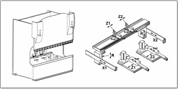
5 . X-Axis Reference Point Adjustment
A) Test the bending of a workpiece, evaluate the X-axis accuracy and calculate the error.
B) Lower the ram below the camber transition point in automatic or manual mode.
C) Adjust the value of the X-axis reference point.
D) Once the machine tool returns to the reference point, confirm the accuracy and use it for normal bending.
6 . Adjustment method in which the X axis is parallel to the lower mold
A) Check that the centers of the upper and lower matrices are aligned;
B) Use the upper mold as a reference, and use a back finger to measure the error at both ends of the X-axis beam. Do not touch the mold with your hand or body.
C) Remove the rear protective cover of the machine.
D) Loosen the screw that fixes the timing belt at the front end of the right side of the press brake's X-axis beam.
E) Fix the right box connector to prevent any movement.
F) Adjust the timing belt to move the screw on the left side of the X-axis beam forward or backward as needed.
G) Use the upper mold as a reference and measure the error at both ends of the X-axis beam with a back finger. Repeat the adjustment process until the error at both ends does not exceed 0.20 mm.
H) Tighten the screws that fix the timing belt on the right side of the box.
I) Loosen the fixings on the right box connector.
J) Return the machine to its reference point.
K) Test workpiece bending and measure X-axis accuracy. Calculate any error.
L) Modify the number of X-axis reference points as needed.
M) After the machine returns to the reference point, test the bending of the workpiece to confirm proper and normal processing.
7 . Y axis reference point adjustment
A) Bend the part and measure the accuracy error of the Y1 and Y2 axes (based on a 90 degree bend);
B) Lower the ram below the camber transition point in automatic or manual mode;
C) Select the Y axis parameter;
D) Adjust the position of the reference point of the Y1 and Y2 axes by approximately 0.07 for each degree;
E) After the machine tool returns to the reference, bend the workpiece again to check the correct and normal processing.
8 . C paddle adjustment
A) Bend the workpiece and measure the intermediate precision error of the workpiece (based on a 90 degree bend).
B) In automatic or manual mode, lower the ram below the camber transition point.
C) Select the CORONATION axis.
D) Adjust the minimum and maximum DA values based on the actual situation.
E) After the machine tool returns to the reference point, bend the workpiece again to confirm whether the processing is correct and normal.
9 . X-axis shake adjustment
A) In automatic or manual mode, lower the RAM below the curvature transition point.
B) Adjust the X-axis gain as needed by reducing it.
C) Once the machine tool returns to the reference point and is operating normally in dry running conditions, part processing can begin.
10 . X-axis movement adjustment is not in place
A) In automatic or manual mode, lower the RAM below the curvature transition point.
B) Adjust (increase) the X-axis gain as needed.
C) Once the machine tool returns to its reference position and operates normally under dry running conditions, part processing can begin.
11 . The beat slides down in the normal state of press the brake machine
1 ) Adjust the reserve pressure valve as follows;
A) Loosen the hexagonal nut on the reserve valve;
B) Adjust the pressure reserve valve adjustment screw;
C) Check whether the ram slip value is normal;
D) Process the workpiece after normal operation.
2 ) Clean the reserve valve as follows;
A) Move the ram to the lowest position using manual mode;
B) Turn off the oil pump engine and turn off the power to the machine;
C) Remove the reserve valve from the valve seat for cleaning;
D) Reinstall the reserve pressure valve after cleaning;
E) Once the machine tool returns to its reference position and is working properly, the part can be processed.
3 ) Replace the reserve valve as follows;
A) In manual mode, lower the ram to the bottom.
B) Turn off the power and oil pump motor of the bending machine.
C) Remove the reserve valve from its seat.
D) Install the new reserve valve.
E) Once the machine tool returns to its reference position, properly adjust the new reserve pressure valve. After a dry test is completed and normal, the workpiece can be processed.
12 . Synchronous servo valve adjustment
1 ) The beater does not move under normal conditions. First check whether the circuit is normal. After confirming the circuit is normal, the servo valve can be detected as follows:
A) Enter the “Valve Test” command and select it.
B) Choose left or right valve.
C) Turn the wheel to change the percentage and observe if the voltage changes.
D) If no changes are observed, clean or replace the synchronous servo valve.
2 ) The cleaning method of synchronous servo valve is as follows:
A) In manual mode, lower the RAM to the bottom.
B) Turn off the oil pump motor and machine power.
C) Disconnect the synchronous servo valve control circuit plug.
D) Unscrew the connection between the synchronous servo valve and the valve seat.
E) Remove the synchronous servo valve and disassemble it, being careful not to break the paint seal.
F) To remove burrs, use metallographic sandpaper to smooth the valve core, ensuring that it moves freely within the valve body.
G) Clean the valve spool with gasoline. Reassemble the synchronous servo valve.
H) Fix the connection between the synchronous servo valve and the valve seat with screws.
I) Reinstall the synchronous servo valve control circuit plug.
J) After installation, test the synchronous servo valve. If it does not work properly, it is recommended to replace it.
K) Once the test is normal, return the machine to its reference position.
L) After successful dry running, the workpiece can be processed.
13 . Filter replacement method
The machine's filter element should be replaced after a specified period of time, every 6 months or after 1,000 working hours, or if the pressure warning cap on top of the filter falls off. The steps to replace the filter are as follows:
A) Lower the ram below the camber transition point in automatic or manual mode;
B) Turn off the power to the machine and the press brake oil pump motor;
C) Open the rear protective cover of the machine;
D) Dismantle the filter;
E) Remove the old filter element, replace it with a new one and tighten the filter;
F) Reinstall the rear protective cover of the press brake;
G) Start the machine and restart the oil pump motor;
H) Let the hydraulic oil filter for 1 hour;
I) The machine can now return to normal processing.
14 . Coronation cylinder replacement method
A) Reduce RAM below the curvature transition point in automatic or manual mode;
B) Turn off the oil pump motor and machine power supply;
C) Open the rear protective cover of the machine;
D) Disconnect the oil tube that connects the crowning cylinder;
E) Remove the protection from the crowning cylinder;
F) Release the support that connects the crowning cylinder and the machine structure;
G) Hit the back of the crowning cylinder with a wooden stick and remove it from the front of the machine;
H) Remove the gasket from the crowning cylinder and install it on the new crowning cylinder;
I) Insert the new crowning cylinder from the front of the machine;
J) Reconnect the crown cylinder oil circuit;
K) Secure the connection between the crowning cylinder and the machine structure using the support;
L) Fix the front cover of the crowning cylinder and the rear protective cover of the machine;
M) Start the machine and restart the oil pump motor;
N) The machine must return to its reference position and be able to process normally.
15 . Hydraulic oil replacement

A) In automatic or manual mode, raise the ram to top dead center and ensure it is properly supported.
B) Turn off the machine and the oil pump motor.
C) Remove the rear protective cover of the machine.
D) Open the shut-off valve at the bottom of the tank to drain the hydraulic oil. Connect the oil tube to the oil outlet on the valve and place the other end of the tube into the oil receiving barrel.
E) Fill new hydraulic oil to the middle of the oil level gauge using the oil filter and hold the ram in the top dead center position.
F) Start the machine and start the oil pump motor.
G) Filter the hydraulic oil for 1 hour.
H) Lower the ram below the camber transition point.
I) Return the machine to its reference position and resume normal operation.
16 . The pressure brake machine does not work
A) The “Emergency Stop” button was pressed.
Solution:
Reset “Emergency Stop” button.
B) A CNC or servo alarm has occurred.
Solution:
Investigate the alarm and take appropriate action.
C) An error message is displayed on the CNC display indicating that Windows initialization was not completed.
Solution:
Inspect the CNC unit to determine the cause of the problem.
D) The control circuit cannot initialize the machine.
Solution:
Diagnose and repair any problems with the control circuit.
17. The pedal is pressed and the beat does not move

A) The pedal is damaged or its cable is damaged.
Solution: Replace the pedal with a new one.
B) The return process is not complete.
Solution: Complete the return referral process.
C) Bottom dead center has not been defined.
Solution: Set bottom dead center.
D) The ram is not in the top dead position.
Solution: Move the ram to its top dead position.
E) The engine is not running.
Solution: Inspect the electrical system.
F) The control circuit is defective or damaged.
Solution: Check the circuit and all its connections.
18. Hitting movement is unstable
A) Incorrect parameter configuration;
Revised Solution:
Check that the parameters are configured correctly.
B) Loose screw connecting the ram;
Revised Solution:
Inspect the connection and tighten the screw(s) as necessary.
C) Defective control device;
Revised Solution:
Inspect and evaluate the control device to determine the problem.
19. When the machine is running, the back gauge parts have abnormal noise
A) Inadequate timing belt tension;
Solution:
Adjust the timing belt tension to the correct specifications.
B) The guide rail and ball screw lack lubricating grease;
Solution:
Lubricate the guide rail and ball screw to ensure smooth operation.
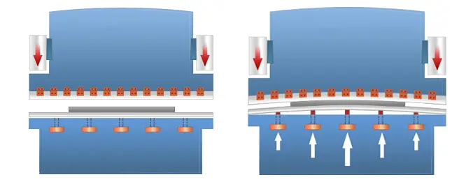
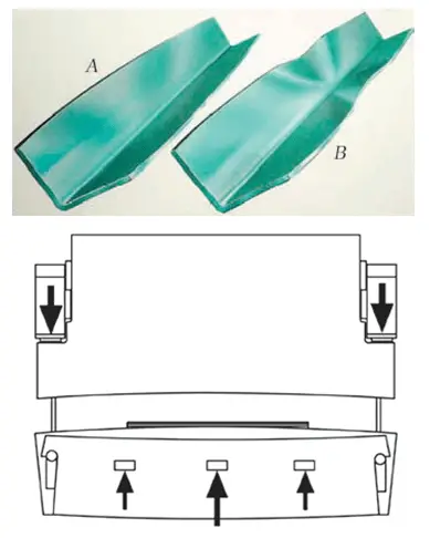
20. The bending angle is different between the middle and the ends
The work table crowning device compensation setting is incorrect;
Revised Solution:
Reset the compensation setting.
21. The bending angles at the ends are different from each other
A) The pressure is too low.
Solution: Increase the pressure.
B) The ram is not parallel in the vertical position.
Solution: Check the initial value of the Y axis and adjust the ram parallelism.
C) Mold parallelism is out of tolerance.
Solution: Adjust or replace the mold and reset the compensation value on the work table.
D) Part quality is inconsistent (e.g., variable thickness).
Solution: Use consistent quality parts.
22. The bending angle is different from the set angle
A) The pressure is too low.
Solution: Increase the pressure.
B) The waiting time is insufficient.
Solution: Extend the waiting time.
C) The warp speed is very slow.
Solution: Increase your bending speed.
D) Part quality is inconsistent (e.g., varying thickness, changes in tensile strength, etc.).
Solution: Use consistent quality parts.
E) The width of the V-shaped opening in the lower die is too narrow.
Solution: Replace the lower die with one that has a wider V-opening.