Brief introduction:
Bending is the process of bending a sheet using a press brake and bending die.
Bending dies, also known as punches or press brake blades, are divided into upper punches and lower dies.
The upper punch is also called the folding blade.
The specific classification of the upper and lower matrices is shown in Figure 1.
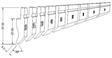
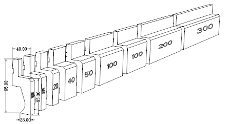
1.Classification and types of the press brake's upper punch : (Fig . 1)
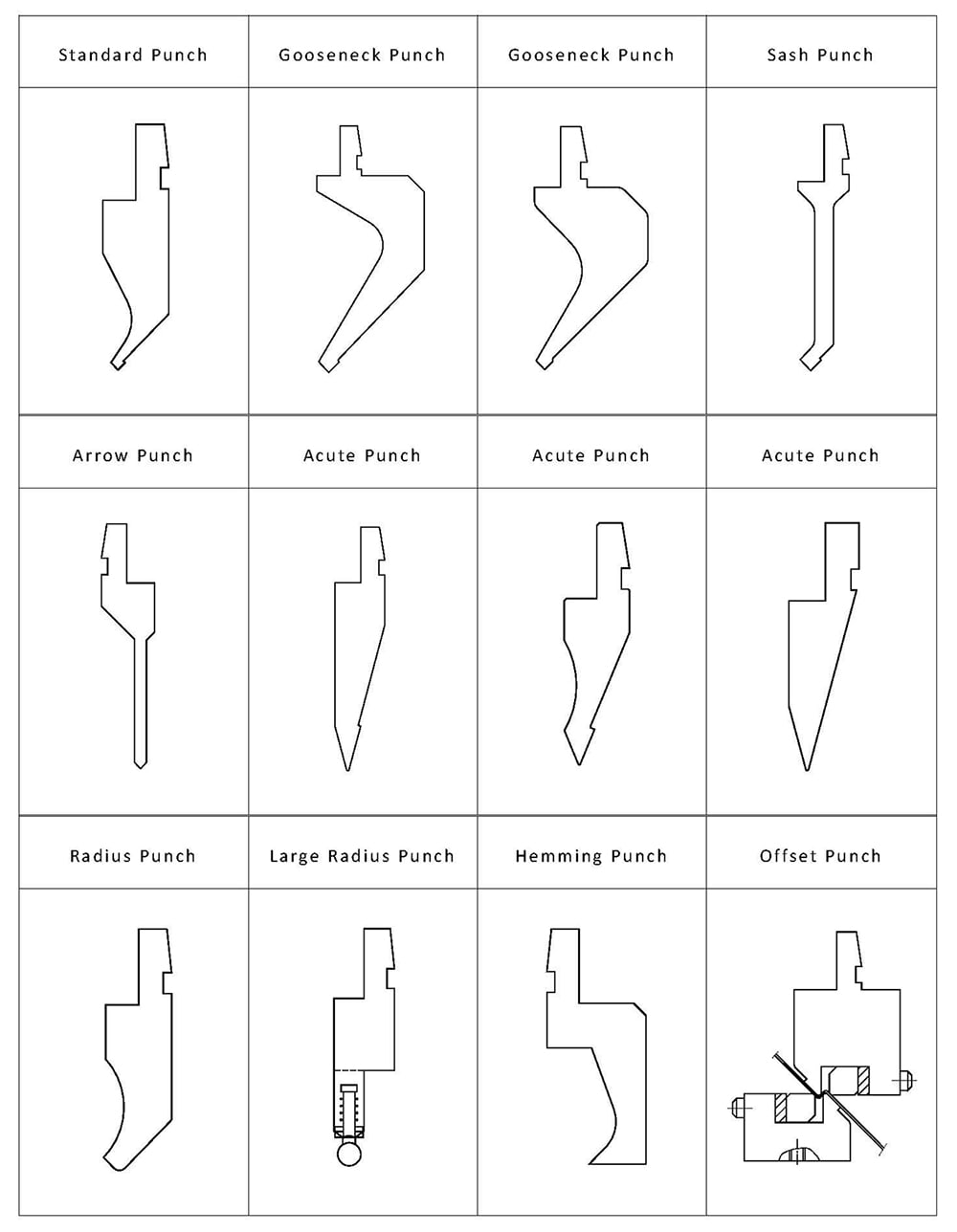
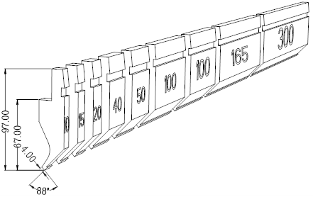
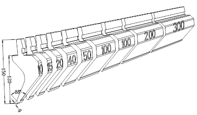
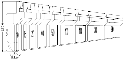
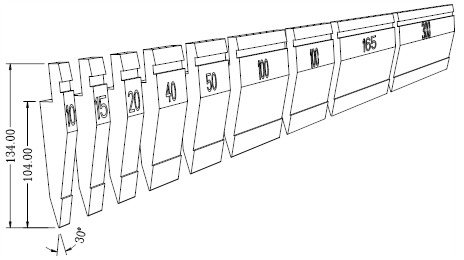
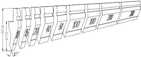
2. The upper punch of the press brake is divided into two types: integral type and segmented type
- Integrated upper punch : 835mm and 415mm
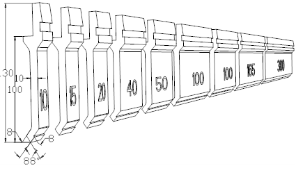
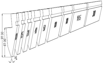
- Segmented upper punch: segmentation a and segmentation b
A divided length: 10,15,20,40,50,100 (right horn),100 (left horn),200,300;
Division B length: 10,15,20,40,50,100(right horn),100(left horn),165,300;
3. Classification and application of various upper punch
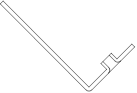
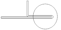
3.1. Gooseneck punch
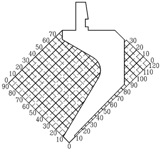
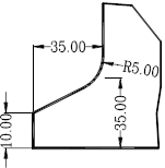
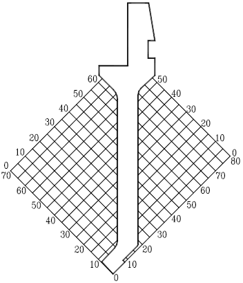
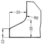
01) Standard gooseneck punch
| Pressure tolerant value (total length) | 20TON/M | Material | 42CrMo | Heat treatment | HRC47±2 |
| Pressure tolerant value (separate) | 11TON/M | Tip radius | 0.2R | ||
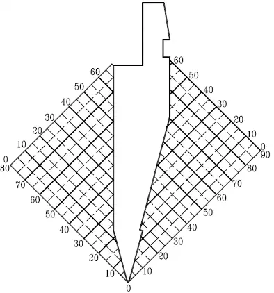
C sort graph (1:1) :
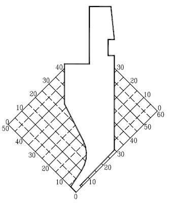
Processing features:
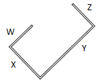
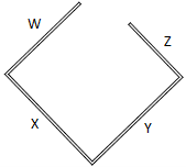
1. The application of standard punch in bending is mainly to avoid the W direction, and the bending diagram is as follows:

2. X direction: when Xmin>4mm, it can be bent (when the size is required in the W direction)
3. Y direction: when 0
Split Chart : Division B
 Horn
Horn
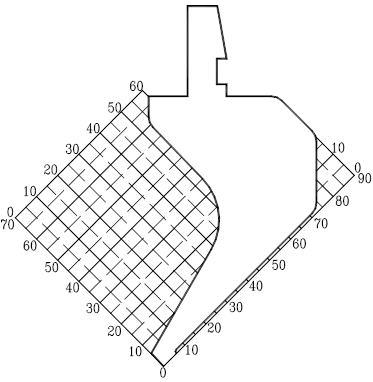
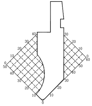
02) Gooseneck punch
| Pressure tolerant value (total length) | 50TON/M | Material | 42CrMo | Heat treatment | HRC47±2 |
| Pressure tolerant value (separate) | 45TON/M | Tip radius | 0.2R | ||
C sort graph (1: 2 )
Processing features:
1. The application of the gooseneck punch in bending is mainly to avoid the W direction, and the bending diagram is as follows:
2. X direction: when Xmin>9mm, it can be bent (when the size is required in the W direction)
3. Y direction: when 0
Split graph: Dividing

 Horn
Horn
03) Gooseneck punch
| Pressure tolerant value (total length) | 50TON/M | Material | 42CrMo | Heat treatment | HRC47±2 |
| Pressure tolerant value (separate) | 30TON/M | Tip radius | 0.2R | ||
C sort graph (0.8:1)
Processing features:
1. The application of the gooseneck punch in bending is mainly to avoid the W direction, and the bending diagram is as follows:

2. X direction: when Xmin>6mm, it can be bent (when the size is required in the W direction)
3. Y direction: When 0
Split graph: Dividing
 Horn
Horn
3.2. Direct Punch
01) Band puncher
| Pressure tolerant value (total length) | 30TON/M | Material | 42CrMo | Heat treatment | HRC47±2 |
| Pressure tolerant value (separate) | 15TON/M | Tip radius | 0.2R | ||
Coordinate plot (0.8:1)
Processing features:
Suitable for bending symmetrical products. Both forward and backward directions can be avoided.
When Xmin>10mm, the W and X directions may increase proportionally.
When 0
When Y>20mm, the Y and Z directions may increase proportionally.
The foldable length in the W direction is greater than the foldable length in the Z direction.
Split Chart : Division B
 Horn
Horn
02) Arrow Punch
| Pressure tolerant value (total length) | 50TON/M | Material | 42CrMo | Heat treatment | HRC47±2 |
| Pressure tolerant value (separate) | 12TON/M | Tip radius | 0.2R | ||
Coordinate plot (0.8:1)
Processing features:
1. Suitable for bending symmetrical products, the front and back directions can be avoided, and the bending opening can be as small as 6mm.
2. When X<50mm,Y<50mm,W and X direction can increase in proportion.

Split Chart : One Split
 Horn
Horn
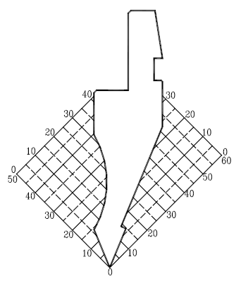
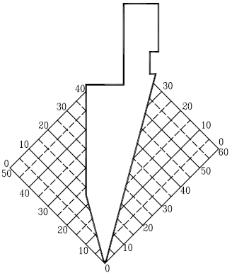
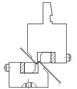
03) Sharp Punch
| Pressure tolerant value (total length) | 100 TON/M | Material | AM87 | Heat treatment | HRC47±2 |
| Pressure tolerant value (separate) | 20TON/M | Tip radius | 0.65R | ||
Coordinate plot (0.8:1)
Processing features:
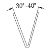
1. The applicable range is between 30° and 180°
2. Use a small angle of the tool tip to avoid the threaded hole and other workpieces that need to be avoided.
3. It is used for deep bending and the insertion depth is suitable for bending angle as shown in the following figure:

Split Chart : Division B
 Horn
Horn
04) Sharp Punch
| Pressure tolerant value (total length) | 60TON/M | Material | AM87 | Heat treatment | HRC47±2 | |
| Pressure tolerant value (separate) | 30TON/M | Tip radius | 0.37R | |||
Coordinate plot (1:1)
Processing features:
1. Suitable for angles between 45° and 180°
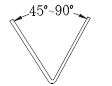
2. Use a small angle of the tool tip to avoid the threaded hole and other workpieces that need to be avoided.

Split Chart : One Split
 Horn
Horn
05) Sharp Punch
| Pressure tolerant value (total length) | 100 TON/M | Material | AM87 | Heat treatment | HRC47±2 |
| Pressure tolerant value (separate) | 30TON/M | Tip radius | 0.52R | ||
Coordinate plot (1:1)
Processing features:
1. The applicable range is between 30° and 180°
2. Use a slight angle of the tool tip to avoid threaded hole

3. For deep bending, the insertion depth is applicable to the bending angle as shown below
Split Chart : Division B
 Horn
Horn
3.3. Lightning punch
01) Radius Puncture
| Pressure tolerant value (total length) | 45TON/M | Material | 42CrMo | Heat treatment | HRC47±2 |
| Pressure tolerant value (separate) | 45TON/M | Tip radius | 1.5R,3.0R | ||
Coordinate plot (1:1)
Processing features:
1. The radius R is 1,5,3,0
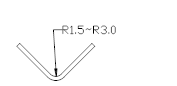
2. Radius punch is often used as pleats for top cover
3. Sometimes used to shape the workpiece with a small angle.
Split Chart: A Split
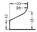
02) Large radius punch
| Pressure tolerant value (total length) | 45TON/M | Material | 42CrMo | Heat treatment | HRC47±2 |
| Pressure tolerant value (separate) | 45TON/M | Tip radius | 3.0R,4.0R5,0R,6.0R,8.0R,10.0R | ||
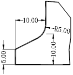
Graph (1:1)
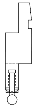
Processing features:
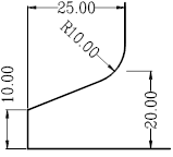
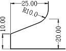
1. This large radius punch is mainly used to bend the inner arc angle of R, and the radius of the arc angle is R3 ~ R10.
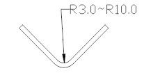
2. The radius punch is compatible with the corresponding V-groove
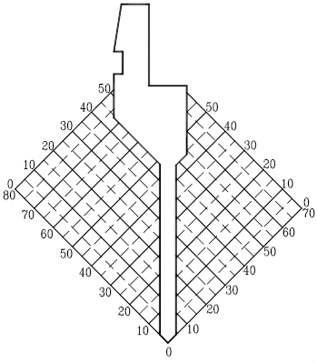
Graphic combination :
3.4. Special Punch
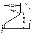
01) Hem Punch
| Pressure tolerant value (total length) | 100 TON/M | Material | 42CrMo | Heat treatment | HRC47±2 |
| Pressure tolerant value (separate) | Tip radius |
Graph (1:1)
Processing features:
1. The diagram in the figure shows the shape of the product after folding and flattening. All similar shapes can be bent. Must be used with upper and lower 30° molds.
2. It can also be used for pressing, riveting, shaping, etc.
Split Chart :
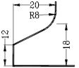
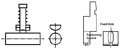
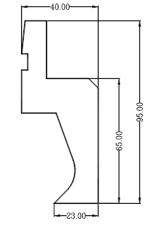
02) Offset drilling
| Pressure tolerant value (total length) | / | Material | 42CrMo | Heat treatment | HRC47±2 |
| Pressure tolerant value (separate) | / | Tip radius | / | ||
Graph (1:1)
Processing features:
1. Used for Z bending that cannot be bent by ordinary bending dies.
H=1~10mm
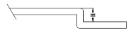
2. The shape of the folded product is shown in the upper right figure, generally called Z-fold or offset.