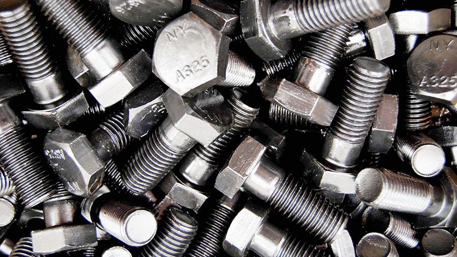

ASTM A325 Bolt Dimensions Table, Sizes, Strength
ASTM A325 bolts are one of the most commonly used fasteners, generally used for structural steel connections in heavy steel structures. It contains two types of hardened and tempered steel heavy hex structural screws:
- Type 1: medium carbon, carbon boron or medium carbon alloy steel,
- Type 3: Heavy-duty steel.
- Type 2: withdrawn in 1991.
The ASTM A325 standard was withdrawn in 2016 and replaced by ASTM F3125/F3125M. Except for dimensions, the information on this page is for reference and historical purposes only.
Properties and Specifications of ASTM A325 Bolts
ASTM A325 material properties and specifications are listed in the following tables, including dimensions, sizes, strength, etc.
Chemical Requirements
| Chemical Requirements for Type 1 Screws, Heat Analysis | ||||||||
| Grades | Material | W | Yes | Mn, ≤ | P, ≤ | S, ≤ | B | Alloy Elements |
| ASTM A325 Type 1 | Carbon steel | 0.30-0.52 | 0.15-0.30 | 0.6 | 0.04 | 0.05 | – | – |
| Boron Carbon Steel | 0.30-0.52 | 0.15-0.30 | 0.6 | 0.04 | 0.05 | 0.0005-0.003 | – | |
| steel alloy | 0.30-0.52 | 0.15-0.35 | 0.6 | 0.035 | 0.04 | – | A | |
| boron steel alloy | 0.30-0.52 | 0.15-0.35 | 0.6 | 0.035 | 0.04 | 0.0005-0.003 | A | |
| Chemical Requirements for Type 1 Screws, Product Analysis | ||||||||
| Grades | Material | W | Yes | Mn, ≤ | P, ≤ | S, ≤ | B | Alloy Elements |
| ASTM A325 Type 1 | Carbon steel | 0.28-0.55 | 0.13-0.32 | 0.57 | 0.048 | 0.058 | – | – |
| Boron Carbon Steel | 0.28-0.55 | 0.08-0.32 | 0.6 | 0.04 | 0.05 | 0.0005-0.003 | – | |
| steel alloy | 0.28-0.55 | 0.13-0.37 | 0.6 | 0.04 | 0.045 | – | A | |
| boron steel alloy | 0.28-0.55 | 0.13-0.37 | 0.6 | 0.04 | 0.045 | 0.0005-0.003 | A | |
ASTM A325 Bolt Strength
The strength of ASTM A325 bolt is summarized in the table below, including tensile strength, yield strength and hardness, etc.
Grades:
The stress area is calculated as follows:
A is = 0.7854 [D-(0.9743/n)]
- A is = tension area, in 2 ,
- D = nominal screw size, and
- n = threads per inch.
| Tensile Requirements for Full-Size Bolts, Studs, and Threaded Rods | ||||
| Bolt size, threads per inch and series designation | Stress Area, in. | Tensile load, lbf, ≥ | Proof load, length measurement method | Alternative proof load, yield strength method |
| 1/2 – 13UNC | 0.142 | 17,050 | 12,050 | 13,050 |
| 05/08 – 11 UNC | 0.226 | 27,100 | 19,200 | 20,800 |
| 3/4 – 10 UNC | 0.334 | 40,100 | 28,400 | 30,700 |
| 7/8 – 9UNC | 0.462 | 55,450 | 39,250 | 42,500 |
| 1 – 8 UNC | 0.606 | 72,700 | 51,500 | 55,750 |
| 1 1/8 – 7 UNC | 0.763 | 80,100 | 56,450 | 61,800 |
| 1 1/4 – 7UNC | 0.969 | 101,700 | 71,700 | 78,500 |
| 1 3/8 – 6 UNC | 1,155 | 121,300 | 85,450 | 93,550 |
| 1 1/2 – 6 UNC | 1,405 | 147,500 | 104,000 | 113,800 |
Tabulated A325 bolt grade loads are based on the following:
| Bolt size, in. | Tensile strength, ksi | Length measurement method, ksi | Yield limit method, ksi |
| 1/2 to 1 | 120 | 85 | 92 |
| 1 1/8 to 1 1/2 | 105 | 74 | 81 |
Hardness Requirements
| Hardness Requirements for Structural Bolts, Studs and Threaded Rod | |||
| Screw size, in | Nominal length, in. | Toughness | |
| Brinell, H.B. | Rockwell B. | ||
| 1/2 – 1 | <2D | 253-319 | 25-34 |
| 2D, ≥ | ≤319 | ≤34 | |
| 1 1/8 – 1 1/2 | <3D | 223-286 | 19-30 |
| 3D, ≥ | ≤286 | ≤30 | |
| D = Nominal diameter or thread size. | |||
A325 Bolt Dimension Table
ASTM A325 bolt dimensions and sizes are listed in the table and drawing below.
Parameter Notes for ASTM A325 Bolts in ASME B18.2.6 -2019


| Table 2.1-1, A325 Heavy Hex Structural Bolts Dimensions | ||||||||||
| Nominal size or basic diameter of the product, inch | Body Diameter (Max-Min), E | Width between apartments, F | Width between corners, G | Head height, H | Fillet radius, R | Thread length, LT | Transition thread length, Y | Maximum Total Deviation of Bearing Surface, END | ||
| Nominal | Max-Min. | Nominal | Max-Min. | |||||||
| 1/2 (0.500) | 0.515-0.482 | 7/8 | 0.875-0.850 | 1.010-0.969 | 05/16 | 0.323-0.302 | 0.031-0.009 | 1.00 | 0.19 | 0.016 |
| 5/8 (0.625) | 0.642-0.605 | 11/16 | 1062-1031 | 1227-1175 | 25/64 | 0.403-0.378 | 0.062-0.021 | 1.25 | 0.22 | 0.019 |
| 3/4 (0.750) | 0.768-0.729 | 1 1/4 | 1,250-1,212 | 1443-1383 | 15/32 | 0.483-0.455 | 0.062-0.021 | 1.38 | 0.25 | 0.022 |
| 7/8 (0.875) | 0.895-0.852 | 7/16 | 1438-1394 | 1660-1589 | 35/64 | 0.563-0.531 | 0.062-0.031 | 1.50 | 0.28 | 0.025 |
| 1 (1,000) | 1.022-0.976 | 1 5/8 | 1625-1575 | 1876-1796 | 39/64 | 0.627-0.591 | 0.093-0.062 | 1.75 | 0.31 | 0.028 |
| 1 1/8 (1.125) | 1,149-1,098 | 113/16 | 1812-1756 | 2093-2002 | 11/16 | 0.718-0.658 | 0.093-0.062 | 2:00 | 0.34 | 0.032 |
| 1 1/4 (1,250) | 1277-1223 | two | 2000-1938 | 2309-2209 | 25/32 | 0.813-0.749 | 0.093-0.062 | 2:00 | 0.38 | 0.035 |
| 13/8 (1,375) | 1404-1345 | 2 3/16 | 2,188-2,119 | 2526-2416 | 27/32 | 0.878-0.810 | 0.093-0.062 | 2.25 | 0.44 | 0.038 |
| 1 1/2 (1,500) | 1531-1470 | 2 3/8 | 2,375-2,300 | 2742-2622 | 15/16 | 0.974-0.902 | 0.093-0.062 | 2.25 | 0.44 | 0.041 |
A325 nut dimensions


| Table 3.1-1, Dimensions of Heavy Hex Nuts for Use with Structural Bolts | ||||||||
| Nominal size or basic main thread diameter, in. | Width between apartments, F | Width between corners, G | Thickness, H | Fillet radius, R | Full runout of FIM bearing face, heavy hex nuts, specified proof load | |||
| Nominal, in. | Max-Min, pol. | Nominal, in. | Max-Min. | <150 ksi | ≥150 ksi | |||
| 1/2 (0.500) | 7/8 | 0.875-0.850 | 1.010-0.969 | 31/64 | 0.504-0.464 | 0.031-0.009 | 0.023 | 0.016 |
| 5/8 (0.625) | 11/16 | 1062-1031 | 1227-1175 | 39/64 | 0.631-0.587 | 0.062-0.021 | 0.025 | 0.018 |
| 3/4 (0.750) | 1 1/4 | 1,250-1,212 | 1443-1383 | 47/64 | 0.758-0.710 | 0.062-0.021 | 0.027 | 0.020 |
| 7/8 (0.875) | 7/16 | 1438-1394 | 1660-1589 | 55/64 | 0.885-0.833 | 0.062-0.031 | 0.029 | 0.022 |
| 1 (1,000) | 1 5/8 | 1625-1575 | 1876-1796 | 39/64 | 1.012-0.956- | 0.093-0.062 | 0.031 | 0.024 |
| 1 1/8 (1.125) | 113/16 | 1812-1756 | 2093-2002 | 17/64 | 1,139-1,079 | 0.093-0.062 | 0.033 | 0.027 |
| 1 1/4 (1,250) | two | 2000-1938 | 2309-2209 | 17/32 | 1251-1187 | 0.093-0.062 | 0.035 | 0.030 |
| 13/8 (1,375) | 2 3/16 | 2,188-2,119 | 2526-2416 | 11/32 | 1378-1310 | 0.093-0.062 | 0.038 | 0.033 |
| 1 1/2 (1,500) | 2 3/8 | 2,375-2,300 | 2742-2622 | 115/32 | 1505-1433 | 0.093-0.062 | 0.041 | 0.036 |
A325 washer dimensions


Table 4.1.1-1, Dimensions for hardened steel circular and circular washers
| Basic size or nominal washer size, inches | Inner diameter, identification | outer diameter, outer diameter | Thickness, T | Minimum distance from edge, E | ||
| Nominal | Max-Min. | Nominal | Max-Min. | Max-Min. | ||
| 1/2 (0.500) | 0.531 | 0.531-0.563 | 1,063 | 1,031-1,095 | 0.097-0.177 | 0.438 |
| 5/8 (0.625) | 0.688 | 0.688-0.720 | 1,313 | 1281-1345 | 0.122-0.177 | 0.547 |
| 3/4 (0.750) | 0.813 | 0.813-0.845 | 1,469 | 1437-1501 | 0.122-0.177 | 0.656 |
| 7/8 (0.875) | 0.938 | 0.938-0.970 | 1,750 | 1718-1782 | 0.136-0.177 | 0.766 |
| 1 (1,000) | 1,063 | 1,063-1,085 | 2,000 | 1937-2063 | 0.136-0.177 | 0.875 |
| 1 1/8 (1.125) | 1,188 | 1,188-1,251 | 2,250 | 2,187-2,313 | 0.136-0.177 | 0.984 |
| 1 1/4 (1,250) | 1,375 | 1375-1438 | 2,500 | 2437-2563 | 0.136-0.177 | 1,094 |
| 13/8 (1,375) | 1,500 | 1500-1563 | 2,750 | 2687-2813 | 0.136-0.177 | 1,203 |
| 1 1/2 (1,500) | 1,625 | 1625-1688 | 3,000 | 2,937-3,063 | 0.136-0.177 | 1,313 |
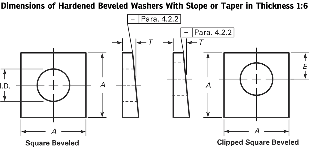

| Table 4.2.1-1, Dimensions of hardened bevel washers with slope or taper in thickness 1:6 | |||||
| Basic size or nominal washer size, inches | Inner diameter, identification | Minimum side length, A | Thickness, T | Minimum distance from edge, E | |
| Nominal | Max-Min. | ||||
| 1/2 (0.500) | 0.531 | 0.531-0.563 | 1.75 | 0.313 | 0.438 |
| 5/8 (0.625) | 0.688 | 0.688-0.720 | 1.75 | 0.313 | 0.547 |
| 3/4 (0.750) | 0.813 | 0.813-0.845 | 1.75 | 0.313 | 0.656 |
| 7/8 (0.875) | 0.938 | 0.938-0.970- | 1.75 | 0.313 | 0.766 |
| 1 (1,000) | 1,125 | 1125-1188 | 1.75 | 0.313 | 0.875 |
| 1 1/8 (1.125) | 1,250 | 1250-1313 | 2.25 | 0.313 | 0.984 |
| 1 1/4 (1,250) | 1,375 | 1375-1438 | 2.25 | 0.313 | 1,094 |
| 13/8 (1,375) | 1,500 | 1500-1563 | 2.25 | 0.313 | 1,203 |
| 1 1/2 (1,500) | 1,625 | 1625-1688 | 2.25 | 0.313 | 1,313 |

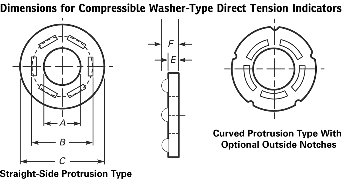
| Table 5.1-1, Dimensions for Compressible Washer Type Direct Tension Indicators, inches | ||||||
| Direct Voltage Indicator Size | All kinds | Types 325-1, 325-3 | Types 490-1, 490-3 | |||
| Inner diameter, A (Min-Max) | Tangential diameter of the protrusion, B, ≤ | Thickness, without protrusion, E, ≥ | With protrusion, F, ≤ | Outer diameter, C (Min-Max) | Outer diameter, C (Min-Max) | |
| 1/2 (0.500) | 0.520-0.527 | 0.788 | 0.104 | 0.18 | 1031-1187 | 1031-1375 |
| 5/8 (0.625) | 0.651-0.658 | 0.956 | 0.126 | 0.22 | 1281-1375 | 1281-1625 |
| 3/4 (0.750) | 0.783-0.790 | 1,125 | 0.126 | 0.24 | 1437-1625 | 1437-1750 |
| 7/8 (0.875) | 0.914-0.921 | 1,294 | 0.142 | 0.26 | 1718-1875 | 1718-2000 |
| 1 (1,000) | 1043-1052 | 1,463 | 0.158 | 0.27 | 1937-2000 | 1937-2250 |
| 1 1/8 (1.125) | 1,174-1,183 | 1,631 | 0.158 | 0.28 | 2,187-2,250 | 2,187-2,500 |
| 1 1/4 (1,250) | 1306-1315 | 1,800 | 0.158 | 0.28 | 2,437-2,500 | 2,437-2,750 |
| 13/8 (1,375) | 1437-1446 | 1969 | 0.158 | 0.28 | 2,687-2,750 | 2,687-3,000 |
| 1 1/2 (1,500) | 1568-1577 | 2,138 | 0.158 | 0.28 | 2,937-3,000 | 2,937-3,250 |
Dimensions of twist-off structural screws


| Table 6.1.1-1, Dimensions of twist-off structural screws: heavy hex head and round head configurations | |||||||||||||
| Nominal size or basic main diameter or thread and thread per inch | Heavy hexagonal head | Heavy Heit and Round Head | round head | Fillet radius, R (Max-Min.) | Thread length, Lr | Spline Length, Ls | Spline width between planes, S | Maximum center of groove to first fully formed thread, U | Transition thread length, Y | Maximum Total Deviation of the FIM Bearing Surface, | |||
| Width between apartments, F (max.-min.) | Width at corners, G (max.-min.) | Head height, H (max-min.) | Full size body diameter. E (Max.-Min.) | Head diameter. D, ≤ | Bearing diameter. C, ≥ | ||||||||
| 1/2 – 13 (0.500) | 0.875-0.850 | 1.010-0.969 | 0.323-0.302 | 0.515-0.482 | 1,126 | 0.89 | 0.031-0.009 | 1.00 | 0.50 | 0.32 | 0.192 | 0.19 | 0.016 |
| 5/8 – 11 (0.625) | 1062-1031 | 1227-1175 | 0.403-0.378 | 0.642-0.605 | 1,313 | 1,102 | 0.062-0.021 | 1.25 | 0.60 | 0.43 | 0.227 | 0.22 | 0.019 |
| 3/4 – 10 (0.750) | 1,250-1,212 | 1443-1383 | 0.483-0.455 | 0.768-0.729 | 1.58 | 1,338 | 0.062-0.021 | 1.38 | 0.65 | 0.53 | 0.25 | 0.25 | 0.022 |
| 7/8 – 9 (0.875) | 1438-1394 | 1660-1589 | 0.563-0.531 | 0.895-0.852 | 1.88 | 1,535 | 0.062-0.031 | 1.50 | 0.72 | 0.61 | 0.278 | 0.28 | 0.025 |
| 1 – 8 (1,000) | 1625-1575 | 1876-1796 | 0.627-0.591 | 1.022-0.976 | 2,158 | 1,771 | 0.093-0.062 | 1.75 | 0.80 | 0.7 | 0.313 | 0.31 | 0.028 |
| 1 1/8 – 7 (1.125) | 1812-1756 | 2093-2002 | 0.718-0.658 | 1,149-1,098 | 2,375 | 1991 | 0.093-0.062 | 2:00 | 0.90 | 0.8 | 0.367 | 0.34 | 0.032 |
| 1 1/4 – 7 (1,250) | 2000-1938 | 2309-2209 | 0.813-0.749 | 1277-1223 | 2.76 | 2,213 | 0.093-0.062 | 2:00 | 1.00 | 0.9 | 0.367 | 0.38 | 0.035 |
ASTM A307 screws, ASTM A572 grade 50 steel, AISI 304 stainless steel


1comment
Preciso saber a resistencia ao corte (cisalhamento) de parafusos de aço inoxidável com 3/4" de diâmetro (o comprimento será 8" (200mm).