Planning and constructing tunnel junctions is a demanding task for planners and the construction team. Let's discuss this in detail.
A tunnel is an underground structure or space created for transportation, water supply, utilities, etc. Tunnels are often built in hydroelectric projects because waterways often pass through rocks. They are constructed as lined or unlined tunnels depending on design requirements arising from geotechnical and other construction aspects.
There is another Article on the Internet about tunnel design and we focus on the planning and construction of tunnel junctions in this article. Nodes in a tunnel are constructed to divert the main tunnel to different sections at different stages or to divide it in two directions.
There are different types of joints in tunnels
- Tunnel divided into segments of equal size: no changes in diameter
- Create a diversion from the main tunnel
The second method is a comparatively difficult construction with variation in diameter compared to the first method. Due to the reduction in diameter, a transition must be built to keep the bottom of the water smooth, as the sudden change in diameter can create turbulence and damage structures, in addition to pressure losses.
Tunnel crossings
Tunnel crossings are built in places where the geometry of the tunnel changes. There are several occasions when crossings are built.
- Change the shape of the circular or semicircular tunnel to a square or other shape.
- Reducing the diameter of a tunnel joint.
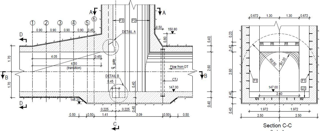
Especially in hydraulic structures, most gate structures are square or rectangular in shape. Therefore, the tunnel has a square or rectangular shape at the beginning and is converted into a normal tunnel shape after the gate structure. The following diagram shows a tunnel connection with a vertical shaft that acts as a gate structure. At the gate the tunnel becomes square and later returns to its original shape with the transition. The shape change can be seen in the CC section.


Furthermore, the following figure shows the diameter variations with geometry changes. One can observe the gradual change from square to circular shape.


Another method for changing the tunnel geometry is explained in detail in this article. The tunnel needs to be fused with another circular geometry and the construction of such a connection is very difficult due to the complexity of the arrangement of reinforcement and formwork. Furthermore, a sudden change in shape could result in pressure losses that could affect power generation if the tunnel were used for this purpose.
Generally, transitions are introduced into joints of this type to ensure a smooth transition of the geometry. The length and diameter of the transition depend on the tunnel diameters and design requirements. The following figure shows this arrangement of the tunnel transition.


Design loads and structural analysis
Tunnel design loads must correspond to the geotechnical conditions of a specific location. The weight of the rock and the grouting pressure can also be considered stresses. Water pressure can be taken into account depending on the condition of the rock and the arrangement of the pipes used to drain the water. For more information on modeling, see the “ Tunnel design ” article.
Structural analysis can be performed using computer-based software, as manual calculations can be too difficult for a structure of this type. The following figure shows images of the structural model created in SAP 2000 software to determine stresses, bending moments, axial forces and shear forces.


A three-dimensional computer model was created using Sap2000 software, and boundary conditions were defined according to the actual arrangement and structural analysis requirements. Load combinations were created for the different load cases considered in the analysis and explained above. The following figures show the bending moment and axial force diagrams obtained in the analysis.


The design was carried out based on bending moments, normal forces, shear forces and other forces.
Design and detailing of reinforcements in tunnel crossings
The design calculation was carried out in accordance with British standards. Special attention was paid to areas where greater concentrations of stress occur. The computational analysis model is also an idealized layout of the real structure. Therefore, the actual arrangements were also taken into consideration during the design. For example, from the connection between two tunnels to the starting point of the transition, the tunnel has a square shape (concrete surface). However, the excavated surface is always circular at the top. Therefore, thickness differences must be taken into account in the design and critical sections must be sized for the highest resulting forces.
The detailing of the reinforcement was carried out in such a way that the reinforcement overload was kept as low as possible, in order to avoid problems during the construction phase. Honeymooning, mud leakage, concreting difficulties, etc. were taken into consideration when preparing the armor drawings.

