Static pressure creates resistance against air movement in the ductwork of an HVAC system, and air handling units must overcome this pressure to provide heating and cooling. Static pressure and airflow are the two main factors that determine how well a fan works and also its energy consumption. For these reasons, calculating static pressure is a very important step in the HVAC design process.
Air ducts are used in many types of HVAC systems, and their design impacts temperature control and energy efficiency. For example, rooftop units (RTU) and fan coil units (FCU) are typically connected to an air duct system. To specify these components correctly, an accurate static pressure calculation is required.
Get a professional static pressure calculation and improve your building's HVAC design.
Even if you have the best air conditioning and space heating equipment on the market, poor air duct design can have a negative impact on your performance. Ventilation systems must overcome static pressure while minimizing noise and vibration. However, static pressure can also be reduced with smart decisions when designing air ducts.

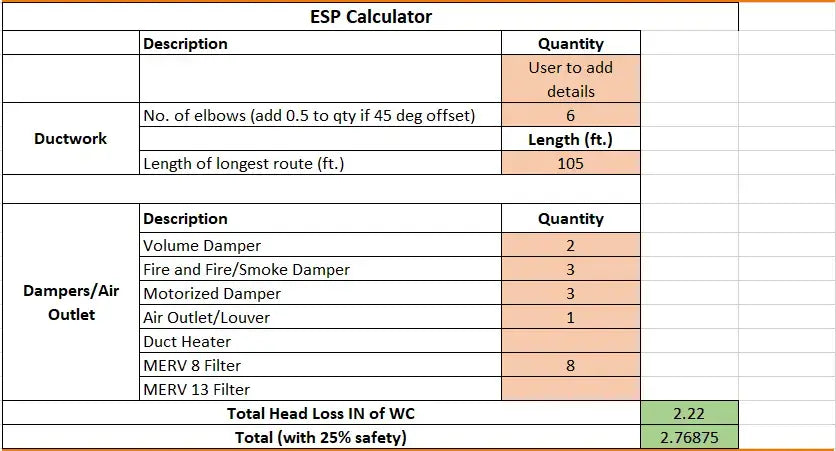
External Static Pressure – ESP Calculation.
External Static Pressure is the measurement of all resistance in the duct system against which the fan must work. Examples are filters, grilles, air conditioning coils and ducts. It is the sum of the suction pressure (negative) and discharge pressure (positive) created by the equipment fan.
Air duct design: a brief overview

Before designing air ducts, HVAC engineers must calculate heat load and air flow according to ASHRAE standards. They must also find ideal locations for diffusers, air handling units, and HVAC equipment. Finally, the air duct layout can be designed according to the available space.
During the pipeline design process, it is very important to avoid conflicts with other building systems, such as electrical and plumbing installations. However, BIM software can detect these issues automatically and engineers can fix them before construction.
The following are some helpful guidelines from HVAC experts when designing air ducts:
- Reduce pressure loss in air ducts as much as possible. This also reduces the required fan power, improving energy efficiency.
- Avoid sudden changes in direction when designing the air duct layout, and provide rotating vanes to minimize pressure drop.
- Minimize noise and vibration as they cause discomfort and distraction to occupants. Vibration also reduces equipment life, leading to expensive repairs.
- Focus on cost-effective design : Save space and materials whenever possible without affecting HVAC performance.
- Design air ducts with an aspect ratio as close to 1 and no more than 4 as possible .
There are three types of air duct systems, classified based on static pressure:
- Low pressure systems, with static pressure up to 2 in. wg
- Medium pressure systems, with a static pressure of 2 to 6 in.
- High pressure systems, with a static pressure greater than 6 in.
Higher static pressure causes more noise and vibration. Ideally, an air duct system should be designed with the lowest static pressure technically feasible.
The Equal Friction Design Method

Three main methods are used to design air duct systems:
- Static recovery method
- Speed method
- Equal Friction Method
The equal friction method is by far the most common in the industry, as it uses simple calculations that are less time consuming. The other two methods are rarely used in modern HVAC projects.
With the equal friction method, air ducts are designed to have a constant pressure drop per unit length , according to the ASHRAE Manual of Fundamentals. Pipeline system friction loss is described by the average pressure drop per 100 feet of pipework.
The ASHRAE Manual allows for some design flexibility by providing charts with suggested ranges of air speed and friction rate. As with any engineering decision, optimal friction and speed depend on design conditions:
- The low friction rate consumes less fan energy but requires larger ducts. This design approach is recommended when electricity is expensive and ducts are accessible.
- The high friction rate consumes more fan energy and saves duct materials. This option is recommended when ducts are expensive and electricity is affordable.
All ducts are initially sized and the pressure loss is then calculated individually for all sections. Based on the results, the air ducts are resized to balance the losses.
How are friction losses classified?

When designing air ducts, friction losses are classified by source – losses caused by the ducts themselves and losses caused by accessories.
- Losses in the duct depend on the air speed and the characteristics of the duct – dimensions, length and roughness of the material. An important step in the design process is identifying the critical path, which is the pipeline path with the greatest pressure loss.
- Adjustment losses represent the largest fraction of total losses. They happen when air passes through filters, displacements, elbows, dampers, coils and other accessories and connections. Using the right accessories in the right locations can lead to significant cost reductions and energy savings. ASHRAE provides appropriate loss coefficients to simplify your selection.
Once all losses are accounted for, HVAC engineers can select a fan that provides the necessary airflow and pressure.
Final Recommendations
HVAC design is very important in construction projects as it impacts long-term operating costs and maintenance expenses. HVAC also represents the largest energy expense for most residential and commercial buildings, and smart design decisions can reduce energy and gas bills. To achieve greater performance, a ventilation system can be equipped with occupancy sensors and variable frequency drives (VFD) for fan speed control.
A well-designed HVAC system also improves occupant comfort, increasing productivity in business environments. HVAC noise can be reduced by selecting optimal duct sizes after an accurate calculation of static pressure.

