The design of axially loaded bolted connections is discussed in detail using a practical example and discussing the technical knowledge associated with the design.
In this article, we focus on the design of steel plates with regular bolt arrangement on which axial tension has been applied.
First, let's discuss the construction method of steel plate with bolts.
Design process
The following steps can be followed during construction.
- Evaluate material properties
First, select a sheet thickness to proceed with construction. Based on the thickness of the plate and the type of steel, the yield strength (f j ) and breaking strength (f Ela ) can be found in Table 3.1 of Eurocode 3.
Then you get the γ m0 and γ m2 from section 6.1. These values may change according to national annexes.
- Calculate the cross section of the plate or the area applying the axial stress.
Different bolt arrangements must be taken into consideration and we must find the critical cross-section with the smallest area that leads to increased stress.

The plate is checked for its gross cross-section and critical cross-section (after reducing the hole area). minimum The following capacity is assumed as the disk capacity (N t,Rd ).
-
-
- N pl, Rd = Af j /γ m0 Gross cross-section plate load capacity (plastic strength). Here is A – gross cross section
- N u, Rd = 0.9A network F j /γ m2 Slab load capacity for gross section (maximum resistance). The following applies here: The network – Net cross section
-
- Check that the disk capacity determined above is less than the applied load.
Disk capacity = (N t,Rd ) = min(N pl, Rd N u, Rd )
Applied Load = N Ed.
N Ed. /N t,Rd <1
Worked example: Construction of a threaded connection; axially loaded plate
Design data
- Load applied to the plate: 300 kN
- Plate thickness 12mm
- Plate width 180mm
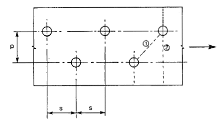
- Screw spacing: s = p = 60 mm (s & p see image above)
- Screw diameter 16mm
- Steel grade S275
For steel grade S275 and sheet thickness 10 mm < 40 mm, the following design parameters can be found in Table 3.1 of EN 1993-1-1 (EC3).
F j = 275 N/mm 2
F She =430 N/mm 2
The partial safety factors result from Section 6.1.
γ m0 = 1.0
γ m2 = 1.25
Plate cross-sectional area
A = 180 x 10 = 1800 mm 2
Plastic resistance N pl, Rd = Af j /γ m0
N pl, Rd = 1800 x 275 / 1.0 = 495000 N = 495 kN
Calculate plate capacity with reduction in hole area

The calculation method for deducing the bolt hole area is presented in Section 6.2.2.2.
It is very easy to calculate the deduction as there is an equation for it.
Deduction = t ( nd 0 – Σ (see 2 /4p) )
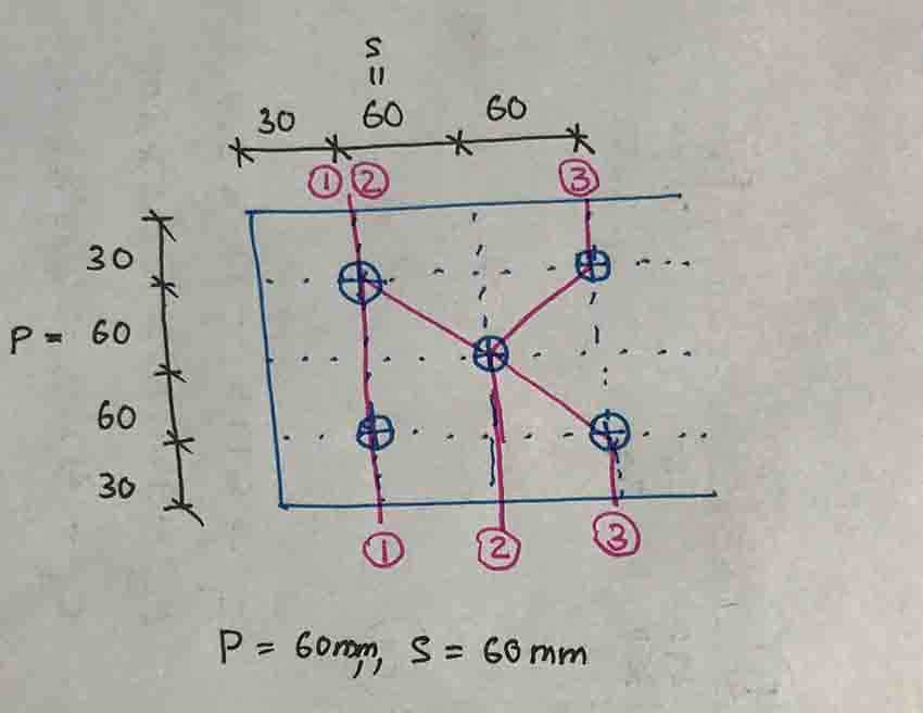
Cross section 1 – 1
Deduction = 10 (2 x 18 – 0) = 360 mm 2
Cross Section 2-2
Deduction = 10 (2 x 18 – (60 2 /4×60) ) = 210 mm 2
Cross section 3-3
Deduction = 10 (2 x 18 – {(60 2 /4×60) + (60 2 /4×60)} ) = 240 mm2
The maximum deduction was in part 1-1
Therefore,
The network = 1800 – 360 = 1440 mm 2
Calculate the maximum resistance, N. u, Rd
N u, Rd = 0.9 x 1440 x 430 / 1.25 = 445824 N = 445.8 kN
Disk capacity = (N t,Rd ) = min(N pl, Rd N u, Rd )
N t,Rd = min(495, 445.8) = 445.8 kN
N Ed. /N t,Rd <1
300/445.8 <1 plate can withstand the applied load.
Also read the article on steel beam design Practical example of constructing a steel beam can be forwarded.