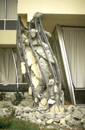
It is common practice to detail structures to improve their ductility and avoid failures due to cyclic loading. Additionally, earthquake-resistant details are created when structures are not designed to withstand seismic loads, even if they are located in non-seismic zones, to avoid possible risks.
According to investigations, the structures failed due to connection errors.
Cyclic loading has a significant impact on structural connections because the highest forces are generated at the connection points.
Figure 01 shows this Column error due to lack of attention to structural detailing.


The main cause of failure is the lack of sealing of structural joints.
Therefore, structural detailing focuses primarily on improving confinement around joints and joints as part of seismic detailing.
All design codes and detailing manuals address this issue.
inclusion
Restraint is achieved by providing connections around the stiffeners. Depending on the type of section, different methods can be used to achieve the limit.


To avoid failures due to cyclic loading, the reinforcement can be limited as shown in Figure 02. Furthermore, confinement increases deformations that lead to concrete failure, as shown in Figure 03.


Therefore, it is very important to pay attention to the limitation of longitudinal reinforcement. Taking this aspect into account, as already explained, reinforcement detailing methods were introduced.
Beam Reinforcement Earthquake Detailing
To detail the reinforcement, delimiting zones are defined near the nodes and non-delimited zones between the delimited zones.
Figure 04 shows the arrangement proposed by the Society of Structural Engineers Sri Lanka to improve structural details.


According to this guideline, it is recommended not to use bent bars and avoid overlapping in the support area.
Furthermore, 50% is recommended as sub-reinforcement in supports in severe earthquake zones and suggests 30% in other zones .
The maximum reinforcement area ratio is limited to 2% or it is recommended to follow BS8110.
Most importantly, the guideline recommends testing shear connections at a distance of 150mm or less for overlaps. It is recommended to avoid crimping beam reinforcement into columns.
Column Reinforcement – Earthquake Resistant Detailing
To obtain information to improve the limitation of the longitudinal reinforcement of the columns, the Sri Lanka Society of Structural Engineers detailing guideline was used.
Figure 05 shows the typical arrangement shown in the guideline.


In addition to the information in Figure 05, the following should be noted.
- The inclination of the column reinforcement in the beam-column connection must be less than 1/6 (in relation to the vertical) when the size of the supports is reduced. If this is the case, the booster should be stopped. The required recommendations for starting and ending rod anchorage lengths specified in the guideline must be followed.
- The distance between the links should be as shown in Figure 5.
- The length of the crank is 10 times the diameter of the rod
- The vertical reinforcement factor of the column must be less than or equal to 4% and must be equal to or greater than 1% . Should be limited to 6% in rounds
- It is recommended to overlap the column reinforcement in the central area.
- If 50% of the column reinforcement overlaps at the bottom of the column (overlaps start at the bottom), the length of the overlap must be equal to or greater than 1.25 times the overall lap length.
- If more than 50% of vertical reinforcement overlaps at the bottom of the column, the overlap length is multiplied by 1.5 .
Stirrups and Anchors in Earthquake Detailing
It is recommended to go through all 135 0 links and have an anchorage as follows. The length of the hook must be measured from the tangent point.
- Planable links – rub or torment 10d or 100mm whichever value is greater. Where d is the diameter of the connection.
- Ribbed bars – grater or 6d or 80mm whatever the grater.
The Wikipedia article Earthquake engineering is most helpful while reading.

