Deep beam sizing according to CIRIA guidelines
Are you looking for a deep beam design? Through research, several guidelines for deep beam designs have been developed. The most commonly used are CIRIA Directive, Eurocode 2, ACI Code, Canadian Code, etc.
This section explains the procedure mentioned in the CIRIA Guide 2. Furthermore, this discussion is based on the book Reinforced Concrete Deep Beams edited by Prof. FK Kong.
The following restrictions must be taken into account when designing beams according to the CIRIA guideline
Single span beam: (effective span/depth ratio ( l /h) less than 2.0.
Continuous beam: (Span/effective depth ratio ( l /h) less than 2.5.
Furthermore, the CIRIA guide could be used with BS 8110;1985.


Effective extension ( I ) results from the following equation
I = I 0 +(less than (C 1 /2 and 0.1 I 0 ) + (less than (C 2 /2) and 0.1 I 0 )
Active altitude ( hA ) can be obtained from the following equation
H A = h or l whichever is smaller
DEEP SUPPORT DESIGN FOR BENDING
STEP 01
Section bending capacity
M Ela = 0.12f cu bra A 2 ; where f cu – strength of the concrete cube, b – width of the beam
STEP 02
If I /H A ≤ 1.5 go to step 03. If I /H A > 1.5 check if the applied moment is less than M Ela
STEP 03
A S >M/0.87f j Z
Where
M = Applied bending moment
F j = Characteristic resistance of the reinforcement
Z = 0.2 l + 0.4 hours A for single-span beams
Z = 0.2 l + 0.3 hours A for continuous beams
STEP 04
The reinforcement area calculated in STEP 03 must be distributed over a depth of 0.2 h. A .
Anchor reinforcement so that at least 80% of the maximum breaking force extends beyond the front of the column.
The main reinforcement must be anchored so that the concrete is sufficiently contained in the support area intended for the support function.
PROJECT FOR SCISSORS
Shear stresses are calculated based on the loading situation.
Beams loaded from below
STEP 01
v Ela = 0.75bh A against Ela
against It is the maximum shear stress of BS 8110 Part 1 Clause 3.4.5.2 and Part 2 Clause 5.4
STEP 02
Check that the applied shear force does not exceed the value V. It
STEP 03
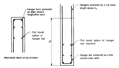
There are hanging rods on both sides to carry the load. The nominal tension of the reinforcements is 0.87f j . Suspended rods must be anchored along the entire length of the composite above the active height h. A or alternatively anchored as tabs around the longitudinal bars at the top. Click here to learn more about designing suspension reinforcement in beams.

STEP 04
The nominal horizontal reinforcement of the web must be predicted to be above the lower half of the active height h. A and at an interval of 0.4h A measured from each support. The area of this web reinforcement shall not be less than 80% of the area of the steel support evenly distributed per unit length. Bar spacing and reinforcement ratio must also meet crack limitation requirements.
Beams loaded from above


STEP 01
Calculate the effective shear margin (x t ), which is the least important thing to pay attention to:
- The shear clearance for a load that contributes more than 50% of the total shear force in the beam
- l /4 with load distributed evenly throughout the span
- The weighted average of free shear spans where more than one load acts and none contributes more than 50% of the shear force in the column. The weighted average is calculated as Σ ( V R
STEP 02
Calculate the shear capacity (V Ela ) from the following equations.
v She = 2bh A 2 against C /X t for H A /b < 4
v Ela = 1.2bh A 2 against C /X t for H A /b ≥ 4
v She = bra A against Her
where v She is the value of BS 8110: Part 1, Section 3.4.5.4 and Part 2: Section 5.4.
STEP 03
Check that the applied shear force does not exceed the shear capacity calculated in step 02.
STEP 04
Provide nominal web reinforcement in the form of a rectangular mesh on each side. The area of nominal reinforcement shall not be less than that specified in BS 8110 Part 1 Clause 3.12.5.3 and Clause 3.12.11.2.9. Additionally, the vertical bars must be anchored as ties around the vertical bars at the edge of the beam. The minimum percentage of reinforcement and bar spacing must also meet crack control requirements.
BEARING DESIGN
Support stress is calculated assuming that the support reaction is uniformly distributed.
Effective support area = (beam width) x (effective support length)
Where
Effective support length = less than (support length or 0.2 l 0 )
Bearing tension should not exceed 0.4f. ass
DESIGN FOR CRACKS
- The minimum percentage of reinforcements must be provided in accordance with BS 8110 Part 1, Section 3.12.5.3 and Section 3.12.11.2.9.
- The maximum spacing between bars must be less than 250 mm.
- The steel content is in a tensile zone P calculated as the ratio of the total area of the steel to the local area of the concrete in which it is embedded must satisfy the condition P > (0.52√f cu )/(0.87f j )
- The maximum crack width should not exceed 0.3 mm under normal environmental conditions. In aggressive environments, the crack width can be 0.2 mm or 0.1 mm. Click here for more information about cracking.