
For civil engineers, foundation stability is one of the most important considerations in the construction of any type of building or structure. A pile cap is an important part of foundation engineering as it provides the necessary support and strength to ensure the stability of the entire foundation. structure.
In this article, we discuss the role of pile caps and the considerations that civil engineers should take into account in their design and construction. We will also discuss the main advantages of pile caps.
What is stack head
Pile caps are essentially large concrete blocks placed on piles to provide support and stability to a structure's foundation. Pile top plates are typically used in deep foundation systems such as: b. Pile foundations when the soil is not strong enough to support the weight of the structure. The block plates are placed on the piles and serve as a transfer point for loads from the structure to the piles.
In many cases, pile heads are also used to resist lateral and thrust forces. Pile heads are usually square or rectangular and usually made of reinforced concrete.
There are different types of blocks designed to support superstructure elements such as concrete pillars, shear walls or other structures. From a single pile, multiple piles can be connected across the top of the pile. The main task is to combine the superstructure and foundation to safely transfer the load from the superstructure to the ground.


Block plate load capacity
One of the most important considerations for civil engineers when designing and constructing pile caps is load capacity. The bearing capacity of a pile cap is determined by the size, shape and number of piles used, as well as the type of soil into which the piles are driven.
Civil engineers must also consider the weight of the structure supported by the block, as well as any other loads the block must support, such as wind and seismic forces.
How to determine the size of a block
There are general standards for determining pile cap sizes. In addition, requirements such as the durability of the block plates are also taken into account.
- Generally, the distance between piles is kept less than three times the pile diameter. This would be useful to apply truss theory and also reduce the generation of bending moments.
- The depth of the block plate is determined based on the applied loads so that shear failure does not occur. There is a preliminary method for calculating the thickness of block plates.
- The distance from the edge or the distance from the pile top plate beyond the pile should be about 100-200 mm. Ideally, we should limit ourselves to 150 mm.
- Reinforcement coverage is determined based on exposure conditions and is not significantly influenced by block dimensions.
How to Design Blocks on Piles
Depending on the type of construction and the loads to be applied, the number of piles per pile head varies. The sizing of the top of the pile is based on the type of load applied and the arrangement of the support.
There are basically three design methods.
1) Truss analogy
Due to its simplicity, this method is most commonly used in pile cap construction. This method does not require many calculations and the calculation method is simple.
There is a simple layering requirement to apply this rule. We generally keep the distance between the piles less than three times the pile diameter. This happens through the main charge transfer mechanism.


As you can see, the angle of the strut with the horizontal must be kept above 45 degrees to apply this theory. The following simplified methods can be used to design the pile caps.
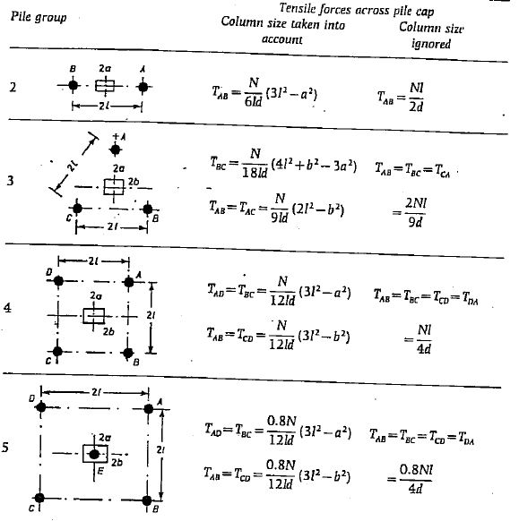

Here you have to calculate the T, which is called T. AWAY etc., which is the tension strap that indicates the tension at the bottom of the block plate.
For example, if the material safety factor for reinforcement is 0.95,
T ABSENT = 0.95f j A S
F j – is the yield strength of the reinforcement
A S – Reinforcement area.
Since we calculated the stress using the above method, a pile cap design can be created from it.
2) Bending theory
If the distance between the posts is large, we cannot use the truss analogy. In these cases we have to use bending theory.
With two batteries it's not that complicated. But things get complicated when there are too many stacks.


In this case, if the column is supported by two piles, we can design the block as a beam. The bending moment and shear forces can be calculated taking into account the column load to design the reinforcement.
3) Computational modeling
As the number of piles increases, manual calculation becomes difficult. Truss theory also cannot be applied to all types of pile heads.
In these cases, we typically use computer software to model the block and determine the bending and shear forces. Punching circumferences are defined manually and shear forces are determined according to the software.
Calculating the block bending moment for many piles can be done manually but is time consuming.


Furthermore, pile loads can also be calculated manually. It is advisable to manually calculate the pile taking into account the center of the load and the geometric center. It would be useful to check the results of the computational analysis.
More complicated blocks are analyzed using computer models. Reinforcement sizing can be done manually.
Special Considerations
Another important aspect that needs to be discussed is providing adequate connection to the tops of the piles. If we consider a tall building, this is a weak connection because we continue with a single post to the ground and the columns along with it. Shear walls will continue as a superstructure.
At this point, we need to connect all the elements to keep them together and held together when significant lateral loads are applied to the building. Therefore, we will properly design floor beams at the pile head level to connect them all.
Images courtesy of the original authors.


